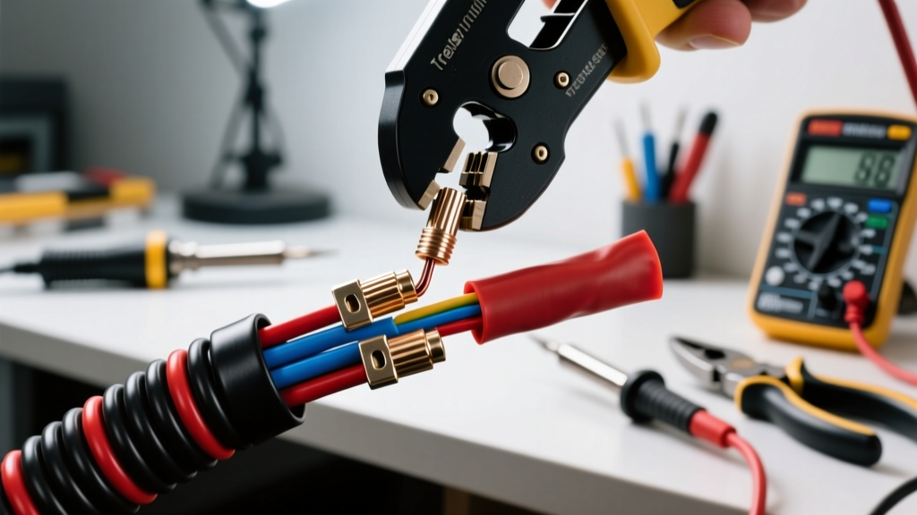
Understanding Tracer Wires in Automotive Harnesses
In modern automotive electrical systems, identifying the correct circuit among dozens of bundled wires is a daily challenge for technicians and DIYers alike. To solve this, manufacturers utilize a tracer wire system. A tracer wire (commonly referred to as a striped wire) features a solid base insulation color with a thin, secondary color stripe—the tracer—running longitudinally down the wire. For example, a wire might be Light Green with a Black tracer stripe. This dual-color coding is critical for tracing circuits back to the ECU, BCM, or trailer tow modules without relying solely on a wiring diagram pinout.
According to the SAE J1128 Standard, which governs low-tension primary automotive cable, these color codes must remain consistent and identifiable throughout the vehicle's lifespan. When a wire breaks, chafes, or requires an extension during a repair, simply cutting out the damaged section and installing a generic, solid-color butt connector destroys the tracer identification. This is where a specialized tracer wire splice kit becomes an essential tool in your electrical repair arsenal.
Why Standard Butt Connectors Fail on Tracer Wires
Beginners often make the mistake of using standard vinyl or nylon-insulated crimp connectors when repairing striped harness wires. This approach introduces three major failures:
- Loss of Circuit Identification: A solid red or blue nylon butt splice covers the base color and the tracer stripe. The next technician (or you, six months later) will have no visual way to identify the circuit's function or destination.
- Moisture Intrusion: Standard crimp connectors are not sealed. Under-hood environments and trailer harnesses are exposed to road salt, humidity, and water spray. Moisture wicks into the copper strands via capillary action, leading to green corrosion and high-resistance voltage drops.
- Insulation Mismatch: Modern vehicles use thin-wall (TXL) or extra-thin-wall (GXL) cross-linked polyethylene wire. Standard bulky connectors do not seal properly over the thinner insulation diameters of 16 AWG and 18 AWG TXL wires, leaving gaps where water can enter.
Anatomy of a Professional Tracer Wire Splice Kit
A high-quality tracer wire splice kit is specifically curated to maintain the electrical integrity and visual identification of striped wires. While contents vary by manufacturer, a professional-grade kit designed for automotive harness repair will include the following components:
- Dual-Wall Adhesive Heat Shrink Butt Splices: These feature an outer layer of polyolefin that shrinks at 120°C (250°F) and an inner layer of thermoplastic adhesive that melts and flows into the wire strands, creating a watertight environmental seal.
- Solder Seal Sleeves: Pre-filled with rosin-core solder and flux, these sleeves melt and bond the copper strands together when heated, providing a vibration-resistant connection preferred by Delphi Automotive Connection Systems for high-current circuits.
- Color-Coded Tracer Tape and Markers: High-temperature, abrasion-resistant vinyl tape strips or specialized electrical marking pens used to recreate the tracer stripe over the clear or black heat shrink tubing.
- Precision Wire Strippers: Calibrated for TXL/GXL thin-wall wire to prevent nicking the copper strands, which reduces the wire's ampacity and creates a weak point.
Step-by-Step: Splicing a 16 AWG Tracer Wire
Let us walk through a real-world repair scenario: fixing a broken 16 AWG Dark Blue with White tracer wire (DK BLU/WHT) commonly used in GM trailer brake controller circuits. Follow these steps to execute a flawless, factory-style repair.
Step 1: Preparation and Stripping
Disconnect the vehicle's battery to prevent short circuits. Cut out the damaged section of the tracer wire. Using precision wire strippers calibrated for 16 AWG thin-wall wire, strip exactly 5/16 inch (8mm) of insulation from both ends. Do not twist the copper strands; twisting alters the crimp profile and prevents the heat shrink from sealing evenly over the wire jacket.
Step 2: Selecting and Crimping the Splice
Select the blue-sized dual-wall adhesive heat shrink butt splice from your tracer wire splice kit (blue indicates 16-14 AWG capacity). Insert one stripped end into the metal barrel and crimp using a ratcheting crimping tool. A proper crimp should yield a slight bellmouth at the wire entry point and pass a firm pull-test. Repeat for the opposite side.
Step 3: Heat Shrinking and Sealing
Using a heat gun set to approximately 250°F (120°C), apply heat evenly around the splice, starting from the center and moving outward toward the wire insulation. Watch closely for the inner adhesive to melt and squeeze out slightly from both ends. This visual confirmation ensures the environmental seal is complete and moisture cannot enter the splice.
Step 4: Re-establishing the Tracer Identification
Once the splice has cooled, you must recreate the tracer stripe. Using the high-temperature white tracing tape included in your kit, apply a thin, continuous strip down the length of the blue heat shrink tubing. Alternatively, use a specialized automotive electrical paint pen to draw a white stripe. This restores the DK BLU/WHT visual code, ensuring the circuit remains identifiable for future diagnostics.
Reference Chart: Common Automotive Tracer Color Codes
Understanding standard color codes is vital when utilizing your tracer wire splice kit. Below is a reference table of common base and tracer combinations found in late-model domestic and import vehicles, particularly in auxiliary lighting and trailer tow harnesses.
| Base Color | Tracer (Stripe) Color | Typical Circuit Application | Common AWG Size |
|---|---|---|---|
| Dark Blue (DK BLU) | White (WHT) | Trailer Brake Output / Electric Brake Controller | 12 AWG - 16 AWG |
| Light Green (LT GRN) | Black (BLK) | Right Turn Signal / Stop Lamp (Trailer) | 16 AWG - 18 AWG |
| Brown (BRN) | White (WHT) | Tail / Marker / License Plate Lamps | 16 AWG - 18 AWG |
| Yellow (YEL) | Black (BLK) | Left Turn Signal / Hazard (Trailer) | 16 AWG - 18 AWG |
| Black (BLK) | Pink (PNK) | Switched 12V Accessory / Ignition Feed | 14 AWG - 16 AWG |
Troubleshooting and Verification
After completing the splice and restoring the tracer identification, you must verify the electrical integrity of the repair before reassembling the vehicle's interior panels or under-hood covers. Visual inspection is not enough; you must perform a voltage drop test.
Reconnect the battery and turn on the circuit (e.g., activate the manual override on the brake controller). Set your digital multimeter to DC Volts. Place the red probe on the power source side of your new splice and the black probe on the load side of the splice. A properly executed splice using a quality tracer wire splice kit should yield a voltage drop of less than 0.05 volts (50 millivolts). If your multimeter reads 0.20V or higher, you have a high-resistance connection. This is typically caused by an incomplete crimp, failure to strip enough wire, or using a connector sized too large for the 16 AWG wire.
Furthermore, consult Molex Automotive Connector Guidelines regarding wire dressing. Ensure the newly spliced wire is routed away from exhaust manifolds, sharp metal brackets, and moving linkages. Use split-loom tubing and high-temperature friction tape to secure the harness back to the factory retaining clips. By combining proper splicing techniques with meticulous wire routing and tracer identification, your repair will match OEM durability and remain easily serviceable for the life of the vehicle.