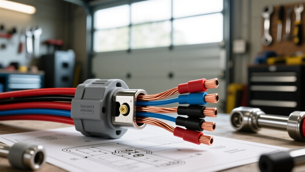
The Problem with Factory T-Taps and Cheap Splices
When executing an upgrade and modification project like installing a high-draw LED light bar, winch solenoid, or auxiliary fuse block on a 4x4, the integrity of your electrical system is only as strong as its weakest junction. Many off-road enthusiasts default to hardware store butt splices, twist-on caps, or insulation-displacement T-taps (Scotch locks). While these may suffice for a stationary garage lamp, they are catastrophic failures waiting to happen in an automotive environment. T-taps slice through the primary wire insulation and strand copper, creating a micro-junction that is highly susceptible to galvanic corrosion, vibration-induced loosening, and moisture ingress. According to the SAE J1128 Low Tension Primary Cable Standard, automotive wire is engineered with specific strand counts and insulation thicknesses to handle under-hood thermal cycling; compromising this insulation invites rapid oxidation and high-resistance faults.
To build a harness that survives water crossings, chassis flex, and extreme engine bay temperatures, you must upgrade your methodology and utilize professional-grade, weather-sealed auto electric wire connectors. This guide details the fabrication of a robust auxiliary lighting harness using industry-standard connector families, precise crimping techniques, and proper circuit protection.
Selecting the Right Auto Electric Wire Connectors for Off-Road Mods
Not all automotive connectors are created equal. For an auxiliary lighting project, you will interface with both low-current relay triggers and high-current power feeds. Selecting the correct connector family ensures environmental sealing and mechanical retention.
Weather-Pack Series (1 to 5 Cavities)
Originally developed by Delphi (now Aptiv Connection Systems), the Weather-Pack series is the gold standard for 14 to 20 AWG circuits. These connectors utilize individual silicone tower seals for each wire and a secondary ribbed seal for the mating interface. They are ideal for relay trigger circuits (Pins 85 and 86), oil pressure sensor pigtails, and dashboard switch extensions. The terminals feature a secondary locking tang that snaps into the plastic housing, preventing 'pin push-out' when the connector is mated.
Deutsch DT Series (2 to 12 Cavities)
For the high-current side of your LED light bar harness (12 to 16 AWG), the Deutsch DT series is mandatory. Unlike Weather-Pack, DT connectors use a single, multi-hole rear grommet seal that grips the outer diameter of the wire insulation. This provides superior strain relief and environmental sealing for heavy-gauge wires exposed to direct water spray and mud. The solid copper alloy pins and sockets offer exceptional conductivity for high-draw accessories.
Metri-Pack 280 Series
When routing 10 to 12 AWG wire from the battery to an auxiliary fuse block or a 40A relay feed (Pin 30), the Metri-Pack 280 series handles up to 30 amps continuously. Its robust blade terminal design resists vibration and thermal expansion better than standard ring terminals in modular fuse block applications.
Project Specifications: Auxiliary LED Light Bar & Fuse Block Integration
Below is the technical specification matrix for upgrading a standard 4x4 auxiliary lighting harness. This setup utilizes a standard ISO 5-pin Bosch-style relay, an inline MAXI fuse, and an auxiliary busbar.
| Circuit Function | AWG Size | Connector Series | Terminal Type | Crimp Tool / Die |
|---|---|---|---|---|
| Relay Trigger (Pins 85/86) | 18 AWG | Weather-Pack 2-Way | Female / Pin | Open Barrel (Delphi) |
| Light Bar Power (Pin 87) | 12 AWG | Deutsch DT 2-Way | Socket / Pin | Closed Barrel (Deutsch) |
| Battery to Fuse Block | 8 AWG | Ring Terminal (3/8 in) | Heavy Duty | 8 AWG Hex Crimp |
| Chassis Ground (Pin 30/85) | 12 AWG | Ring Terminal (5/16 in) | Standard | Closed Barrel |
Note: Always use SAE J1128 compliant cross-linked polyethylene (XLPE) insulated wire, such as GXL or TXL, which offers superior heat and chemical resistance compared to standard PVC wire.
Step-by-Step Harness Fabrication and Crimping Masterclass
The physical act of crimping is where most modification projects fail. A proper crimp creates a cold-weld gas-tight seal between the terminal barrel and the copper strands, preventing oxygen from reaching the metal and causing resistance.
- Precision Stripping: Use a thermal wire stripper or a high-quality automatic stripper calibrated to the exact AWG. Never nick the copper strands. A nicked 12 AWG strand reduces the tensile strength and creates a localized hot spot under high amperage loads.
- Open Barrel Crimping (Weather-Pack): Place the terminal in the open-barrel crimp tool. The tool forms two distinct crimps: the conductor crimp (which folds the brass wings tightly around the bare copper, forming a bellmouth at the front and back) and the insulation crimp (which wraps around the wire jacket for strain relief). The front bellmouth should be visible to ensure no strands are trapped under the insulation crimp.
- Closed Barrel Crimping (Deutsch DT): Insert the wire into the machined barrel of the DT terminal. Use a 4-way indent crimp tool. The tool compresses the barrel into a hexagonal or B-shape, cold-welding the copper. A proper closed-barrel crimp should withstand a pull-test force exceeding 45 lbs for 12 AWG wire without the wire slipping.
- Seal Insertion: For Weather-Pack, slide the silicone tower seal over the wire before crimping. The seal must sit flush against the insulation crimp wings. For Deutsch DT, the rear grommet is pushed into the housing after the terminals are locked in place using the orange or green plastic wedges.
- Adhesive Heat Shrink: Where wires transition from split loom to the connector backshell, apply dual-wall, polyamide-lined heat shrink tubing. As you apply heat, the inner adhesive melts and flows into the wire strands, creating a 100% waterproof capillary barrier. Standard PVC heat shrink will eventually crack and wick moisture into the harness.
Routing, Looming, and Physical Protection
Once your auto electric wire connectors are mated and your harness is assembled, physical routing dictates longevity. Never zip-tie a harness directly to a moving suspension component, steering shaft, or high-voltage ignition coil pack. Wrap the harness in abrasion-resistant Tesa harness tape or nylon braided sleeving. When passing through the firewall or metal bulkheads, always use a rubber grommet and apply a dab of silicone dielectric grease to prevent the sheath from chafing against raw steel edges, which inevitably leads to a dead short.
Troubleshooting Matrix: Common Failure Modes and Diagnostics
Even with premium components, environmental extremes can cause faults. Use this diagnostic decision tree when troubleshooting your upgraded lighting circuits:
- Symptom: Intermittent flickering of the LED bar over rough terrain.
Cause: Pin push-out or loose insulation crimp allowing the terminal to back out of the housing.
Fix: Use a dedicated pin extraction tool to release the locking tang. Verify the secondary lock (TPA/CPA) is fully seated. Recrimp the insulation grip if the wire slides. - Symptom: Green/white crust (galvanic corrosion) visible inside the connector cavity.
Cause: Moisture ingress past the silicone seal due to an undersized wire OD or missing seal.
Fix: Cut back the oxidized wire. Ensure the wire insulation diameter perfectly matches the inner diameter (ID) of the silicone seal. Pack the mating interface with dielectric grease to displace oxygen and water. - Symptom: Voltage drop across the connector resulting in dim lights.
Cause: High resistance from an undersized crimp die, oxidized mating surfaces, or using tin-plated terminals for high-draw circuits instead of silver or nickel-plated.
Fix: Perform a millivolt drop test across the mated connector while the circuit is under load. A healthy connector should drop less than 10mV per connection point. If higher, replace the terminals and ensure your crimp tool is calibrated to the manufacturer's AWG specifications.
Final Verification
Before applying power to your newly fabricated harness, perform a continuity and dead-short test using a digital multimeter. Verify that your 8 AWG battery feed has a clean, star-washered ground point directly to bare chassis metal, painted surfaces act as insulators and will cause severe voltage drop. By abandoning cheap splices and investing in professional auto electric wire connectors, proper crimp tooling, and meticulous routing, your 4x4 modification project will achieve OEM-level reliability, ensuring your auxiliary systems perform flawlessly whether you are on the highway or deep in the backcountry.