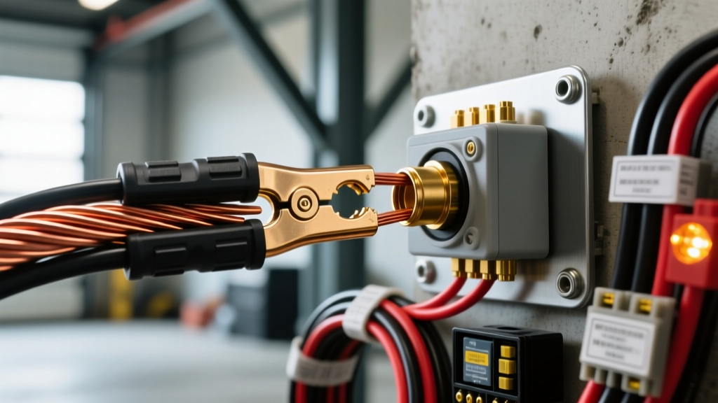
The Hidden Bottleneck in Aftermarket Lighting Upgrades
When enthusiasts tackle off-road lighting modifications—whether swapping factory H4 halogen bulbs for high-draw H9 upgrades or installing a 50-inch curved LED light bar—the focus is almost entirely on lumen output and beam patterns. However, the most critical component of any high-amperage automotive modification is often overlooked: the car wire connector. Relying on factory pigtails, cheap butt splices, or non-sealed terminal strips for auxiliary lighting is a guaranteed recipe for voltage drop, melted housings, and eventual electrical failure.
Factory headlight wiring is typically engineered with minimal overhead. A standard 55W halogen bulb draws roughly 4.5 amps. Automakers use 18 AWG or even 20 AWG primary wire to save weight and copper costs, routing it through multi-pin, unsealed cabin connectors. When you introduce a 40A relay harness to drive a set of 100W off-road pods, pushing 16+ amps through undersized wire and inadequate connectors generates severe resistive heat. To execute a professional-grade upgrade, you must integrate heavy-duty, weather-sealed connectors into your custom harness build.
Comparing Weatherproof Car Wire Connector Systems
Not all automotive connectors are created equal. For underhood and exterior chassis modifications, the connector must resist moisture ingress, vibration, and extreme thermal cycling. According to SAE International J1128 standards for low-tension primary cable, underhood environments demand insulation and termination methods that can withstand continuous temperatures up to 125°C. Below is a comparison of the three most common sealed connector systems used in automotive modification projects.
| Connector System | Max Amperage | Supported AWG | Sealing Mechanism | Best Modification Use Case |
|---|---|---|---|---|
| Delphi Weather-Pack | 20A per pin | 10 to 20 AWG | Individual silicone cable seals + tower housing | High-amp relay harnesses, battery terminals, winch solenoids |
| Deutsch DT Series | 13A per pin | 14 to 20 AWG | Rear wire seal grommet + hard dielectric shell | LED light bar pigtails, cabin pass-throughs, sensor extensions |
| Sumitomo TS Series | 15A - 30A | 12 to 22 AWG | Matte-seal interface + individual wire seals | OEM-style ECU repinning, headlight adapter harnesses |
For a custom 40A auxiliary lighting relay harness, the Delphi Weather-Pack remains the gold standard. Its robust nylon housing and individual silicone tower seals provide superior strain relief and IP67-level moisture resistance, making it the ideal car wire connector for high-current switching applications.
Project Build: Custom 40A Relay Harness Using Weather-Pack Connectors
This section outlines the construction of a heavy-duty relay harness designed to bypass factory headlight switches, delivering full battery voltage directly to auxiliary off-road lights. We will use a standard Bosch-style SPDT (Single Pole Double Throw) 40A relay, terminated with 2-pin and 3-pin Weather-Pack connectors.
Material Specifications and Wire Sizing
Always use TXL (Thin-wall Cross-linked) or GXL automotive primary wire. TXL features cross-linked polyethylene insulation rated for 125°C, offering superior abrasion and heat resistance compared to standard PVC wire. Avoid copper-clad aluminum (CCA) wire; insist on 100% oxygen-free bare copper.
- Pin 30 (Battery Feed): 12 AWG TXL, Red. (Capable of handling 40A continuous with minimal voltage drop over short runs).
- Pin 87 (Load to Lights): 12 AWG TXL, Blue.
- Pin 85 (Ground): 16 AWG TXL, Black.
- Pin 86 (Trigger Signal): 16 AWG TXL, Yellow.
- Terminals: Tin-plated brass Weather-Pack male/female terminals (Tin plating prevents galvanic corrosion when exposed to road salt and moisture).
- Seals: Green silicone cable seals (for 12 AWG) and Grey silicone cable seals (for 16 AWG).
Step 1: Precision Stripping and the 'F-Crimp' Science
The reliability of any car wire connector relies entirely on the quality of the crimp. Weather-Pack terminals utilize an open-barrel design that requires a specific crimping profile. You must use a dedicated open-barrel crimper (such as the Delphi OEM tool or a high-quality aftermarket equivalent like the IWISS open-barrel die set).
The terminal features two distinct crimp zones:
- The Conductor Crimp (Front): This section folds over the bare copper strands to form an 'F' shape. The crimp height must be precisely calibrated. For 12 AWG wire, the target crimp height is 0.085 inches; for 16 AWG, it is 0.055 inches. An under-crimp will cause high resistance and localized heating; an over-crimp will sever copper strands, reducing the effective wire gauge and creating a mechanical weak point.
- The Insulation Crimp (Rear): This section forms a rounded 'U' or 'O' shape around the wire jacket. It provides zero electrical conductivity but is vital for strain relief, ensuring that vibration does not transfer mechanical stress to the conductor crimp.
Step 2: Housing Insertion and Cavity Sealing
Once crimped, slide the appropriate silicone cable seal over the wire before crimping the terminal (a common beginner mistake is forgetting the seal). After crimping, push the terminal into the nylon connector housing. You must push firmly until you hear and feel a distinct tactile 'click', indicating the terminal's locking tang has engaged the housing's internal retaining shoulder.
Critical Modification Rule: If you are using a 3-pin Weather-Pack housing but only populating 2 pins (for example, on the relay's trigger side), you must insert a blank silicone cavity plug into the empty slot. Leaving a cavity open compromises the connector's environmental seal, allowing moisture to enter via capillary action, which will eventually corrode the adjacent populated terminals.
Routing, Looming, and Environmental Protection
According to TE Connectivity engineering guidelines for harsh environment interconnects, even fully sealed connectors benefit from secondary physical protection. Route your newly built harness away from exhaust manifolds, steering shafts, and sharp chassis edges. Wrap the 12 AWG and 16 AWG legs in split-loom corrugated tubing, and secure the tubing with nylon cable ties every 8 inches. Where the harness passes through the firewall to reach the cabin trigger switch, use a rubber grommet and apply a bead of silicone RTV to prevent water from wicking into the cabin along the wire jacket.
Troubleshooting Matrix: Voltage Drop and Connector Failures
Even with premium components, installation errors can cause failures. Use the following diagnostic matrix to troubleshoot issues in your modified lighting harness.
| Symptom | Probable Cause | Diagnostic Fix |
|---|---|---|
| Lights dim significantly at idle but brighten when revving the engine. | Excessive voltage drop across the car wire connector due to a loose conductor crimp or undersized wire. | Perform a voltage drop test across the connector with a multimeter under load. A healthy connection should show less than 0.1V drop. Re-crimp if higher. |
| Connector housing is warm to the touch or shows brown melt marks. | Terminal oxidation, improper crimp height, or using 16 AWG wire on a 30A+ circuit. | Inspect the terminal locking tang. If the terminal backed out slightly, it increases resistance. Replace the terminal and verify wire gauge matches the amperage load. |
| Lights flicker randomly over rough terrain. | Terminal locking tang failed to engage, or insulation crimp is too loose, allowing wire movement. | Pull gently on the wire. If the terminal slides out of the housing, use a terminal extraction tool to remove it, bend the locking tang outward slightly, and re-seat it. |
| Corrosion (green/white crust) inside the sealed housing after 6 months. | Missing cavity plug, or wire jacket diameter was too small for the silicone seal, breaking the IP67 seal. | Measure the wire OD with calipers. Ensure the seal matches the wire insulation diameter, not just the AWG rating, as TXL thin-wall insulation has a smaller OD than standard PVC. |
Final Verification
Upgrading your vehicle's lighting architecture requires treating the electrical system as a complete, integrated network. By selecting the correct heavy-duty car wire connector, adhering to strict crimping tolerances, and utilizing TXL wire, you ensure that your off-road modifications perform flawlessly in the harshest environments. Always conclude your project by testing the entire circuit with a thermal imaging camera; run the lights for 15 minutes and scan the connectors. Any terminal glowing hotter than the ambient wire indicates a high-resistance crimp that must be redone before hitting the trail.