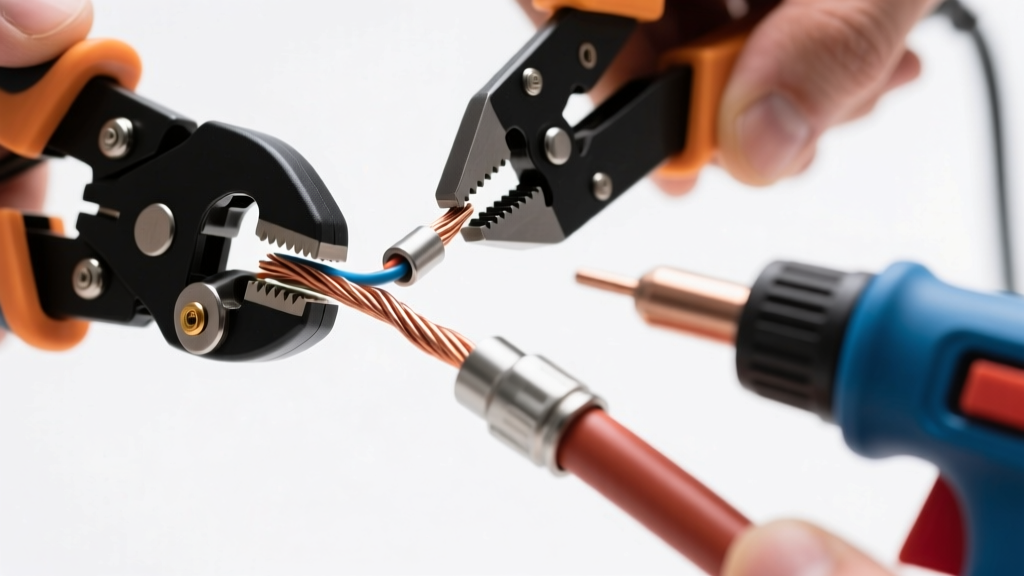
Why Small Gauge Splices Require Specialized Techniques
Modern automotive electrical systems rely heavily on low-amperage, high-sensitivity circuits. From 5-volt reference signals feeding MAP and TPS sensors to high-speed CAN-bus networks and wideband oxygen sensor signal lines, these circuits typically utilize 20 to 24 AWG (American Wire Gauge) or even 26 AWG wiring. When a wire breaks or a pigtail requires replacement, using standard 16-14 AWG crimp tools and oversized butt connectors on these micro-circuits is a recipe for disaster.
Oversized crimps fail to compress the small wire strands adequately, leading to 'cold crimps'—mechanical connections with high electrical resistance. In a 5V reference circuit, an extra 0.5 ohms of resistance from a poor splice can alter the voltage drop enough to trick the ECU into logging phantom misfires, false lean codes, or erratic transmission shift points. Furthermore, engine bay environments subject these splices to extreme thermal cycling, high-frequency vibration, and corrosive road salts. Mastering the installation of small wire splice connectors is essential for any automotive electrical technician aiming for permanent, OEM-quality repairs.
Essential Tools for Micro-Circuit Splicing
Before attempting to splice 22 AWG or 24 AWG sensor wires, you must discard standard hardware store crimpers. Precision requires specialized tooling.
1. Precision Wire Strippers
Standard strip-cutters often nick the copper strands of small gauge wires, reducing the cross-sectional area and creating a weak point that will snap under engine vibration. Use precision micro-strippers, such as the Knipex 12 42 195 or Engineer PA-20, which feature exact-dimension cutting blades that score the insulation without touching the copper core.
2. Ratcheting Micro-Crimp Pliers
A ratcheting mechanism ensures a full-cycle crimp every time, preventing the 'half-crimp' failure mode where the tool releases before maximum compression is achieved. Tools like the IWISS SN-28B or specific Molex Hand Crimping Tools feature micro-dies designed specifically for 0.08mm² to 0.5mm² terminals and splices.
3. Adhesive-Lined Dual-Wall Heat Shrink
Standard PVC insulation tape or single-wall heat shrink is unacceptable for under-hood sensor repairs. You must use dual-wall polyolefin heat shrink with an inner layer of thermoplastic adhesive. When heated, the outer wall shrinks while the inner wall melts, filling all voids and creating a completely waterproof, dielectric seal.
Small Wire Splice Connector Sizing Chart
Selecting the correct barrel size is critical. If the wire is too loose in the barrel, it will pull out. If forced, the strands will splay and short against adjacent pins. Reference this chart based on SAE J1128 Low Tension Primary Cable Standards:
| Wire Gauge (AWG) | Metric Cross-Section | Typical Automotive Application | Splice Connector Color / Type | Strip Length |
|---|---|---|---|---|
| 24 - 26 AWG | 0.14 - 0.22 mm² | CAN-Bus, Airbag Clock Springs | Yellow Micro-Butt / Step-Down | 4.0 mm |
| 20 - 22 AWG | 0.34 - 0.50 mm² | O2 Sensor Signals, 5V Ref, IAT | Red Micro-Butt | 5.0 mm |
| 18 - 20 AWG | 0.50 - 0.75 mm² | Injector Pigtails, Solenoids | Blue Standard / Step-Down | 6.0 mm |
Step-by-Step Installation Guide: Mechanical Crimping
Follow this procedure to ensure your small wire splice connectors meet the rigorous pull-test and environmental standards outlined in the IPC/WHMA-A-620 Wire Harness Assembly Standards.
- Wire Preparation: Strip the insulation to the exact length specified in the chart above. Crucial Rule: Never twist the exposed copper strands. Twisting alters the lay of the wire, reduces the surface area for the crimp barrel to bite into, and violates IPC-A-620 standards. The strands should remain parallel as they exited the insulation.
- Connector Selection: Choose an adhesive-lined heat shrink butt splice. For joining a 22 AWG sensor wire to a 18 AWG harness wire, use a 'step-down' splice connector featuring a larger diameter barrel on one end and a micro-diameter barrel on the other.
- Insertion and Inspection: Insert the stripped wire into the metal barrel. Look through the semi-transparent heat shrink or the inspection window of the crimp tool. The copper strands must be flush with the end of the metal barrel, but not protruding so far that they risk shorting out.
- The Conductor Crimp: Place the metal barrel into the appropriately sized micro-die of your ratcheting crimp tool. Squeeze until the ratchet releases. The die should fold the metal barrel inward, creating a cold-weld where the copper strands and the brass/tin barrel become a single solid mass.
- The Insulation Crimp: If your connector features a secondary insulation grip, crimp it over the wire's outer jacket to provide strain relief. This prevents engine vibration from transferring directly to the delicate metal crimp joint.
- Thermal Sealing: Using a precision heat gun set to approximately 120°C (250°F), apply heat starting from the center of the splice and moving outward toward the edges. Stop heating the moment the adhesive melt-wall squeezes out slightly from both ends. This visual indicator confirms a complete environmental seal against moisture and dielectric fluids.
Alternative Method: Solder Seal Splice Connectors
In tight harness wraps where a mechanical crimp tool cannot fit, solder seal splices (solder sleeves) are an acceptable alternative for small gauge wires. However, they require careful thermal management.
These connectors feature a pre-formulated solder ring in the center and adhesive rings on the edges. To install, slide the sleeve over one wire, twist the bare strands together (a rare exception to the no-twist rule, required here for solder wetting), slide the sleeve over the joint, and apply heat. Warning: Avoid excessive heat on small wire splice connectors of this type. If the wire insulation is thin (like PTFE on Bosch LSU 4.9 wideband O2 sensors), excessive heat will cause capillary action, wicking the molten solder under the wire insulation. This makes the wire brittle and prone to snapping inches away from the splice.
Real-World Application: Repairing a CAN-Bus Pigtail
Consider a repair on a Ford MS-CAN network, which utilizes 22 AWG twisted pair wiring (typically Gray/Orange for CAN-High and Gray/Brown for CAN-Low). CAN-bus relies on differential signaling, which requires the wires to be tightly twisted to cancel out common-mode electromagnetic interference (EMI).
When splicing these small wires:
- Keep the untwisted 'pigtails' as short as physically possible (under 15mm).
- After crimping and sealing the small wire splice connectors, you must re-twist the repaired section. Aim for at least 1 twist per inch (approx. 2.5 cm) to maintain the 120-ohm characteristic impedance of the network bus.
- Failure to re-twist will result in signal reflection, causing U-codes (e.g., U0100 Lost Communication with ECM) when the vehicle hits high-speed data transmission thresholds.
Common Failure Modes and Diagnostic Testing
Even with the correct small wire splice connectors, errors can occur. Use this diagnostic matrix to troubleshoot sensor circuit issues post-repair:
| Symptom | Probable Cause | Diagnostic Fix |
|---|---|---|
| Intermittent P0335 (CKP Circuit) | Strands nicked during stripping; thermal expansion breaks the weakened copper under hood heat. | Perform a voltage drop test across the splice while wiggling the harness. Replace splice using precision micro-strippers. |
| O2 Sensor Heater Code (P0030) | Used a 22 AWG micro-splice on a 16 AWG heater circuit, causing a high-resistance bottleneck. | Verify AWG size. Heater circuits draw 8-15 Amps and require standard blue/yellow butt splices, not micro-splices. |
| U0155 (Lost Comm with IPC) | Solder wicked under insulation via capillary action, creating a rigid stress point that snapped. | X-ray or physically bend-test the wire 1 inch from the splice. Cut back to flexible copper and use a mechanical crimp. |
Final Verification
Never rely solely on a visual inspection or a basic continuity beep from a multimeter. A single strand of 24 AWG copper can pass a continuity test but will instantly voltage-drop under the actual load of a solenoid or sensor bridge. Always perform a dynamic voltage drop test across your small wire splice connectors with the key on, engine running, and the circuit actively loaded. A properly crimped and sealed micro-splice should exhibit a voltage drop of less than 0.05V, ensuring your repair is invisible to the vehicle's ECU and built to survive the harsh automotive environment.