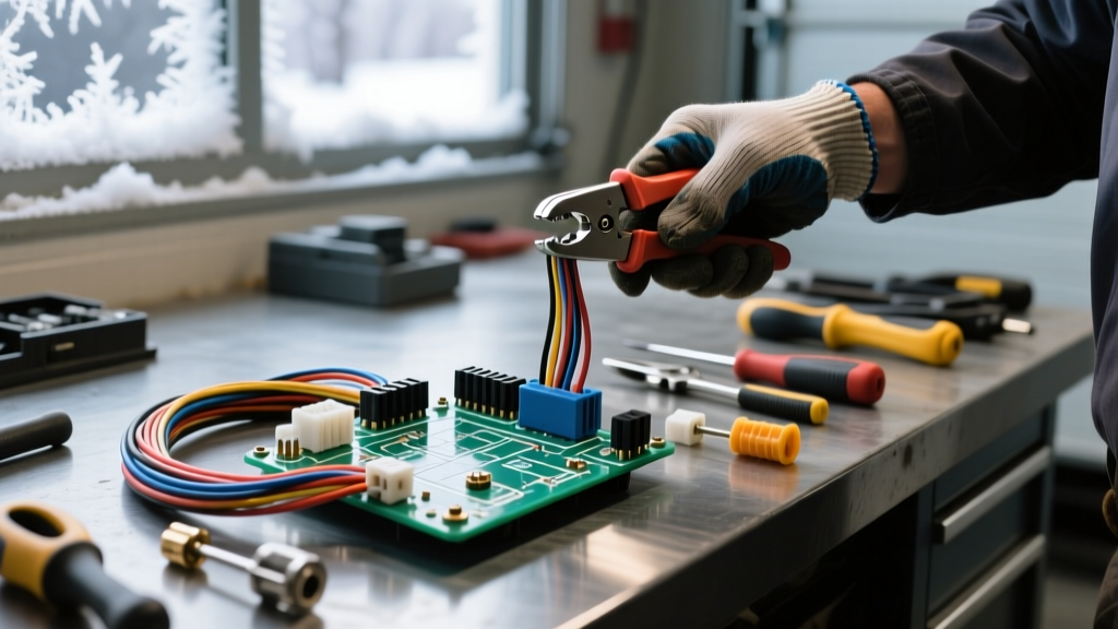
Why Local Climate Dictates Your Wiring Strategy
If you have been searching for auto electrical repair Princeton guides to fix your daily driver, you already know that local weather plays a massive role in vehicle longevity. In regions like Princeton, New Jersey, the combination of heavy winter road salt (sodium chloride), frequent freeze-thaw cycles, and high humidity creates a highly corrosive environment for automotive electrical systems. Standard, non-sealed butt connectors and cheap electrical tape will inevitably fail here. Saltwater acts as an electrolyte, accelerating galvanic corrosion between copper wire strands and brass or bronze connector terminals.
For beginners stepping into automotive wiring, understanding how to properly seal, crimp, and route wires is the difference between a permanent fix and a recurring parasitic draw or open circuit. This guide covers the fundamental techniques required to rebuild damaged circuits using professional-grade, weather-sealed connectors.
The Beginner’s Toolkit for Connector Repair
Before cutting into a single wire, you must assemble the correct tools. Improper crimping is the leading cause of high-resistance connections in DIY auto electrical repair.
- Precision Wire Strippers: Avoid standard household pliers. Use ratcheting automotive wire strippers calibrated for 22 AWG to 10 AWG to prevent nicking the copper strands.
- Open-Barrel or Closed-Barrel Crimpers: Delphi (now Aptiv) Weather-Pack terminals require a specific closed-barrel crimper with an oval or hexagonal die. Metri-Pack terminals often utilize open-barrel crimpers. Using the wrong die will result in a cold crimp that vibrates loose under the hood.
- Terminal Extraction Tools: A set of pin removal tools (like the Lisle 39960 set) is mandatory. Never use a flathead screwdriver to pry out a locked terminal, as this will permanently deform the plastic housing's locking tang.
- Adhesive-Lined Heat Shrink: Standard PVC heat shrink is useless for under-hood repairs. You must use dual-wall, adhesive-lined polyolefin heat shrink with a 3:1 or 4:1 shrink ratio. When heated, the inner wall melts and seals out moisture, while the outer wall provides abrasion resistance.
Step-by-Step: Rebuilding a Corroded Headlight Connector
Let us walk through a common scenario: repairing a melted or corroded 2-pin headlight connector on a late-90s to early-2000s GM truck, a frequent victim of Princeton's salted roads. The circuit typically uses 14 AWG wire (approx. 2.0 mm²) to handle the 10-12 amp draw of a standard halogen H11 or 9006 bulb.
Step 1: Excising the Damage and Prepping the Wire
Cut the wiring harness at least two inches behind the corroded connector. Strip exactly 5/16" (8mm) of insulation from the 14 AWG wire. If the copper appears black or green further down the harness, capillary action has drawn moisture deep into the jacket. You must continue cutting back until you see bright, shiny copper. Slide a piece of adhesive-lined heat shrink onto the wire before crimping the new terminal.
Step 2: Precision Crimping the Terminal
Automotive terminals feature two distinct crimp zones: 1. The Conductor Crimp: This grips the bare copper strands. It must be tight enough to deform the strands into a solid mass (creating a gas-tight seal that prevents oxygen from causing internal corrosion) but not so tight that it shears the copper. 2. The Insulation Crimp: This wraps around the wire's PVC jacket to provide strain relief, ensuring that any pulling force is absorbed by the jacket, not the delicate copper strands.
Place the 14 AWG Weather-Pack terminal into the correct die of your crimper. Squeeze until the ratcheting mechanism releases. Inspect the crimp: the wire strands should be slightly visible at the front of the conductor crimp, confirming the wire was fully seated.
Step 3: Sealing and Terminal Insertion
Slide the adhesive heat shrink over the terminal barrel and the wire insulation. Apply heat evenly with a heat gun (not a lighter) until the adhesive oozes slightly from both ends. Next, push the terminal into the plastic connector housing. You must hear and feel a distinct "click" as the terminal's locking tang engages the plastic retaining bridge. Gently pull back on the wire to verify it is locked in place.
Reference Chart: Automotive Connector Environmental Ratings
Choosing the right connector family is critical for long-term reliability. The following table outlines the most common sealed connectors you will encounter in auto electrical repair.
| Connector Family | Typical AWG Range | Environmental Rating | Common Automotive Applications |
|---|---|---|---|
| Delphi Weather-Pack | 14 to 20 AWG | IP67 (Dust-tight, temporary immersion) | Older GM headlight circuits, horn relays, exterior lighting |
| Delphi Metri-Pack 150 | 18 to 22 AWG | IP6K9K (High-pressure steam wash) | Modern engine sensors (O2, MAF, TPS), fuel injectors |
| Deutsch DT Series | 14 to 20 AWG | IP68 (Continuous immersion) | Heavy-duty trucks, off-road lighting, marine applications |
| Molex MX150 | 18 to 22 AWG | USCAR-2 / IP6K9K | Modern ECU connections, airbag modules, interior harnesses |
For more detailed specifications on terminal retention forces and environmental testing, refer to the SAE International J1128 standard for low-tension automotive wire, or consult TE Connectivity's automotive connector documentation for precise mating cycle data.
Understanding Terminal Extraction and Pin Configurations
Beginners often struggle with removing a single bad pin from a multi-pin connector without breaking the housing. Automotive connectors utilize a primary lock (the metal tang on the terminal) and often a secondary lock (a plastic TPA - Terminal Position Assurance insert).
Extraction Procedure:
- Remove the TPA lock if present. This usually requires prying it up gently with a small pick.
- Insert the correct hollow extraction tool over the terminal face. The tool's job is to compress the metal locking tang (or barbs) inward, flush with the terminal body.
- Push the tool in until it bottoms out, then pull the wire straight out from the back of the connector. Never pull from the front.
- If the terminal resists, do not force it. You are likely using the wrong tool profile (e.g., using a square tool on a D-shaped Metri-Pack terminal).
Verifying the Repair: Voltage Drop Testing
After rebuilding your connector, you must verify the integrity of the repair. A visual inspection is not enough; internal corrosion or a loose crimp can cause a voltage drop that mimics a bad ground or a failing component.
Set your digital multimeter to DC Volts. Connect the red probe to the battery positive terminal and the black probe to the component side of your newly repaired 14 AWG wire (with the headlight turned ON). A healthy wire and connector should exhibit a voltage drop of less than 0.10V (100mV). If you read 0.5V or higher, your crimp is insufficient, or the terminal is not fully seated in the housing, creating a high-resistance bottleneck that will eventually melt the plastic connector under the heat generated by Ohm's Law (P = I²R).
Final Thoughts on Preventative Maintenance
Successful auto electrical repair in harsh climates requires a proactive approach. Once your connectors are rebuilt and tested, apply a small amount of dielectric grease (such as Permatex or NYE 812) to the mating face of the connector. This hydrophobic compound displaces moisture and prevents the formation of zinc oxide or copper sulfate on the terminal blades. By mastering these beginner-friendly fundamentals, you ensure your vehicle's electrical system remains resilient against the harshest winter conditions.