Decoding Splice Nodes on Automotive Schematics
When troubleshooting an automotive electrical fault, the wiring diagram is your primary roadmap. However, a schematic does not just show components; it maps out the exact physical topology of the harness, including hidden junction points. Before you can physically repair a circuit, you must understand how to read these junction nodes and identify the different types of wire splices used by the manufacturer. In a factory harness, splices are rarely accessible without cutting back loom and tape, making the schematic's node identifiers critical for pinpointing failure zones.
Different manufacturers use distinct nomenclature for splice nodes on their diagrams:
- General Motors (GM): Uses an 'S' prefix followed by a three-digit number (e.g., S101, S205). The first digit typically denotes the harness location (1 = Engine, 2 = Instrument Panel, 3 = Body).
- Ford: Represents inline splices with a solid black dot where wires intersect on the schematic, often accompanied by a splice pack identifier if located in a junction block.
- Toyota/Chrysler: Frequently utilizes 'Splice Packs' or 'Junction Blocks' denoted by a boxed node with multiple pinouts branching outward.
Understanding these symbols tells you whether you are chasing a simple inline ultrasonic weld buried in the harness tape, or a removable splice pack connector that can be serviced without cutting wires.
Evaluating Different Types of Wire Splices for Diagram Repairs
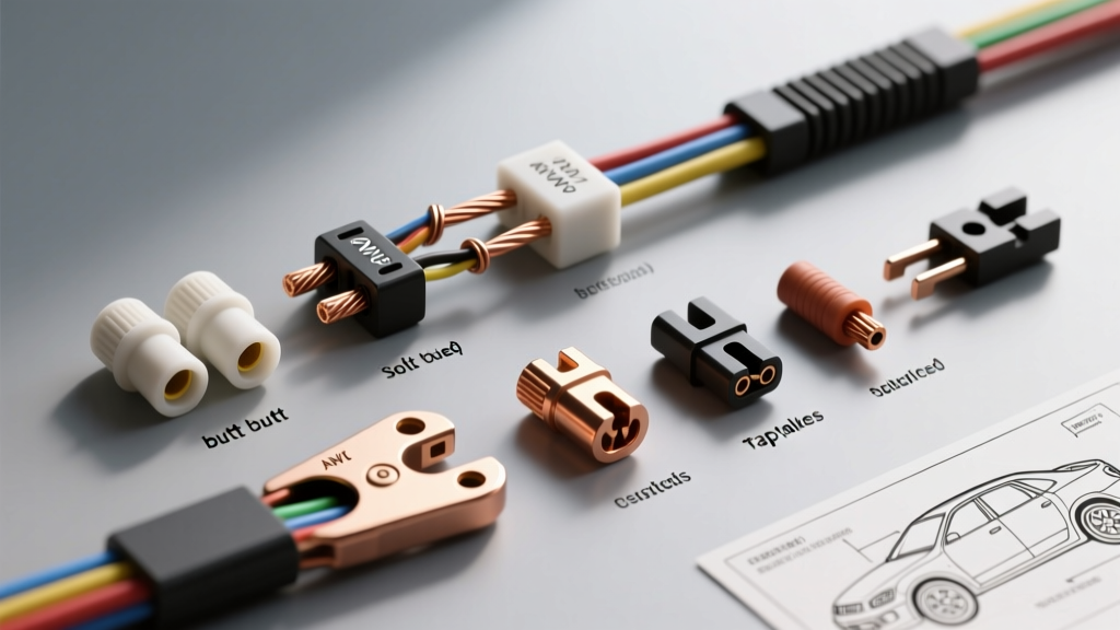
When a wiring diagram leads you to a failed splice node, selecting the correct repair method is dictated by the circuit's current load, vibration profile, and AWG (American Wire Gauge) size. According to SAE J1128 standards for low-tension primary cables, maintaining the mechanical and electrical integrity of the original harness is paramount. Here is a breakdown of the different types of wire splices you will encounter and execute in the field.
1. Ultrasonic Weld Splices (Factory OEM Standard)
If your schematic points to a node buried deep within a main harness trunk, you are likely dealing with an ultrasonic weld. This factory process uses high-frequency acoustic vibrations to fuse bare copper strands together under pressure, creating a solid-state metallurgical bond without solder or filler metal. It offers the lowest voltage drop and highest pull-out strength. When repairing an ultrasonic node in the aftermarket, we cannot replicate the weld, so we substitute it with a sealed parallel crimp or a step-down butt connector.
2. Adhesive Heat-Shrink Butt Crimps (Aftermarket Harness Repair)
The industry standard for repairing inline schematic nodes is the dual-wall, adhesive-lined heat-shrink butt splice. When heated to approximately 120°C, the outer polyolefin tubing shrinks while the inner meltable adhesive flows into the wire strands, creating a watertight seal. This is the required method for repairing 18 AWG to 12 AWG sensor and power circuits exposed to engine bay temperatures and moisture.
3. Soldered Lap Splices (Low-Vibration / High-Current)
While many technicians default to soldering, modern OEM guidelines (including Delphi Automotive Wiring Systems documentation) warn against using solder in high-vibration zones. Solder wicks into the wire strands via capillary action, creating a rigid transition point just outside the splice. In an engine harness, this stiffened section will eventually suffer from copper fatigue and snap. However, soldered lap splices remain acceptable for rigid terminal repairs or interior cabin circuits where vibration is minimal.
4. Step-Down Splices (Gauge Transitions)
Wiring diagrams frequently show a heavy-gauge feed wire (e.g., 12 AWG) splicing into multiple lighter-gauge distribution wires (e.g., 18 AWG). A standard butt connector will fail to crimp the smaller wires securely. Step-down splices feature a larger barrel on one side and a smaller barrel on the other, or a single large barrel designed to accept one 12 AWG and two 18 AWG wires simultaneously, mirroring the factory 'Y' splice node shown on the schematic.
Walkthrough: Repairing an S205 Oxygen Sensor Circuit
To demonstrate how to translate a schematic into a physical repair, let us walk through a common fault: a P0036 (HO2S Heater Control Circuit Bank 1 Sensor 2) on a GM LS-based V8 engine.
Step 1: Tracing the Schematic
Looking at the GM wiring diagram, the O2 sensor heater circuit originates at Fuse F23 (15A) in the underhood bussed electrical center. The power feed exits as an 18 AWG Pink wire. Following the Pink wire down the schematic, we see it hits node S205. At S205, the single 18 AWG Pink wire splits into two 18 AWG Pink wires: one feeding Bank 1 Sensor 2, and the other feeding Bank 2 Sensor 2.
Step 2: Locating the Physical Node
The diagram's harness routing legend indicates S205 is located approximately 150mm from the main engine harness breakout, wrapped in convoluted loom and friction tape. Because both O2 heater circuits share this node, a corrosion failure at S205 will often cause simultaneous heater codes for both banks, or a voltage drop that prevents the sensors from reaching closed-loop operating temperature.
Step 3: Executing the Splice Repair
Once the harness is opened and the corroded ultrasonic weld at S205 is exposed, the damaged copper must be cut back to clean, shiny metal. Because we are joining one feed wire to two distribution wires, we must select the correct splice type:
- Strip the Wires: Strip 5/16-inch of insulation from the main 18 AWG Pink feed and the two 18 AWG Pink sensor feeds.
- Select the Connector: Use a 16-14 AWG heat-shrink butt connector. The combined cross-sectional area of two 18 AWG wires (approx. 1,600 circular mils) fits perfectly into the 16-14 AWG barrel alongside the single 18 AWG feed wire.
- Crimp the Joint: Using a ratcheting crimp tool calibrated for heat-shrink terminals (such as those outlined in Molex Hand Crimp Tooling Guidelines), crimp the barrel. The ratchet ensures the copper strands are compressed to the exact manufacturer specification without cutting the wire.
- Seal the Splice: Apply heat evenly with a micro-torch or heat gun until the adhesive bleeds out of both ends of the tubing, ensuring complete environmental sealing against engine oil and road salt.
Splice Selection Matrix for Automotive Schematics
| Schematic Node Type | Wire Gauge (AWG) | Recommended Repair Splice | Typical Circuit Application |
|---|---|---|---|
| Inline 'Y' Split (e.g., GM S-Node) | 18 to 14 AWG | Adhesive Heat-Shrink Butt / Step-Down | Sensor feeds, injector harnesses |
| Heavy Power Feed Junction | 10 to 4 AWG | Ultrasonic Weld or Heavy-Duty Copper Lug | Alternator outputs, starter feeds |
| Splice Pack / Junction Block | 20 to 16 AWG | Replace Terminal Pins (Do not cut wires) | CAN-bus networks, interior lighting |
| Shielded Cable Drain Wire | 22 to 24 AWG | Soldered Lap Splice with Kapton Tape | Audio signals, high-speed data lines |
Common Diagnostic Pitfalls When Tracing Spliced Circuits
When performing a complete wiring diagram walkthrough, technicians often make critical errors at splice nodes that lead to recurring electrical faults:
- Ignoring CAN-Bus Splice Rules: If your schematic shows a splice on a High-Speed GMLAN or CAN-H/CAN-L circuit, standard butt splices will alter the characteristic impedance of the twisted pair, causing data bus reflections and communication DTCs (e.g., U0100). These nodes must be repaired using specific soldered joints with minimal untwisting of the pair (no more than 10mm).
- Misidentifying Ground Splices: Schematics often group multiple ground wires into a single node (e.g., GM G101) before terminating at a chassis bolt. Technicians sometimes mistake this schematic node for an inline wire splice and attempt to repair it inside the harness, rather than cleaning the physical ring terminal connection to the engine block.
- Overlooking Wire Color Tracers: At a factory splice node, the wire color may change. A schematic will show a 'Pink/Black' wire splicing to a 'Brown' wire. If you are probing for voltage and only looking for solid Pink, you will misdiagnose the circuit downstream of the splice.
Mastering the translation between the 2D wiring diagram and the 3D physical harness requires a deep understanding of these splice methodologies. By respecting OEM node designs and utilizing the correct adhesive-lined, gauge-specific crimps, you ensure the repaired circuit matches the factory schematic's electrical parameters, eliminating voltage drop and preventing future harness degradation.