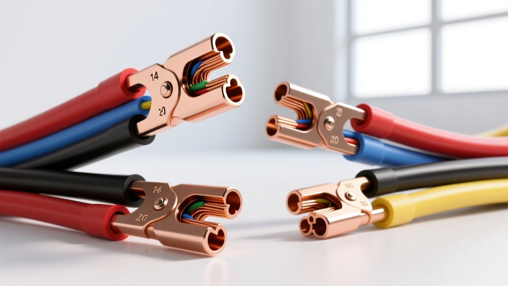
The Metallurgy of Cold Welding in Automotive Splices
When discussing automotive butt splice wire connectors, it is critical to understand that a proper crimp is not merely a mechanical compression; it is a gas-tight metallurgical bond known as cold welding. Under the immense localized pressure exerted by a calibrated crimping die, the copper strands and the tinned copper barrel of the connector deform plastically. This deformation fractures the microscopic layers of copper oxide and environmental contaminants on the wire surfaces, allowing the raw copper atoms to intermingle and form a gas-tight seal. According to the IPC/WHMA-A-620 standard, a properly executed cold weld prevents oxygen and moisture ingress, effectively eliminating galvanic corrosion at the splice junction. In automotive environments characterized by extreme thermal cycling and high-frequency vibration, relying on solder for mechanical strength is a critical failure point. Solder wicks into the wire strands via capillary action, creating a stiff transition zone that concentrates stress and leads to strand fracture. Therefore, high-quality butt splice wire connectors rely entirely on the mechanical and metallurgical integrity of the crimp, reserving the heat shrink tubing solely for environmental sealing and strain relief.
AWG Sizing, Barrel Geometry, and USCAR Tensile Specifications
Automotive primary cable, such as GXL (General Cross-Linked) and TXL (Thin Cross-Linked) wire specified under SAE J1128, requires precise barrel geometry to achieve optimal compression ratios. The connector barrel must be sized so that the wire fills the void space entirely without crushing the individual strands to the point of shearing. Below is the reference specification chart for standard automotive butt splice wire connectors, including the minimum tensile pull-out forces mandated by USCAR-21 standards for low-tension primary circuits.
| Color Code | AWG Range | Metric Cross-Section | Wire Strip Length | USCAR-21 Min. Pull-Out Force | Optimal Crimp Width |
|---|---|---|---|---|---|
| Red | 22-18 AWG | 0.35 - 0.82 mm² | 6.0 mm (0.24 in) | 50 N (11.2 lbs) | 2.8 mm |
| Blue | 16-14 AWG | 1.04 - 1.65 mm² | 7.0 mm (0.28 in) | 130 N (29.2 lbs) | 3.6 mm |
| Yellow | 12-10 AWG | 2.62 - 4.11 mm² | 8.5 mm (0.33 in) | 300 N (67.4 lbs) | 4.8 mm |
Deviating from these strip lengths results in either 'insulation flash' (where the wire insulation is caught inside the crimp barrel, causing high resistance) or 'conductor protrusion' (where bare copper is exposed outside the heat shrink zone, inviting corrosion).
Dual-Wall Adhesive Heat Shrink Chemistry
The environmental sealing of automotive butt splice wire connectors relies on dual-wall polyolefin heat shrink tubing. Unlike single-wall tubing, which only provides basic abrasion resistance, dual-wall tubing features an inner layer of thermoplastic adhesive. The outer cross-linked polyolefin layer has a shrink initiation temperature of approximately 90°C, while the inner adhesive layer has a melt flow index designed to liquefy at around 120°C. When heated correctly, the outer jacket shrinks radially, forcing the molten inner adhesive into the interstitial voids between the copper strands and the wire insulation. This creates an IP67 and IP69K rated environmental seal capable of withstanding high-pressure washdowns and submersion in road salt brine. For high-temperature engine bay applications, technicians must verify that the adhesive melt temperature does not exceed the thermal rating of the underlying TXL or GXL wire insulation, which is typically rated for 125°C to 155°C continuous operation.
Tooling Calibration: Ratcheting vs. Indent Crimpers
Achieving the gas-tight seal required for butt splice wire connectors necessitates the use of precision ratcheting crimp tools. Non-ratcheting pliers rely entirely on operator hand strength, leading to inconsistent compression ratios and latent failure modes. Ratcheting tools feature a mechanical release mechanism that prevents the jaws from opening until the full crimp cycle is completed, ensuring the die reaches the exact dimensional specification. For stranded automotive wire, a hex-crimp or quad-point crimp die profile is preferred over an indent crimp. Indent crimpers, which drive a single punch into the barrel, are designed for solid-core wire and will sever the delicate strands of 16-14 AWG stranded GXL wire, drastically reducing the current-carrying capacity and tensile strength of the splice.
Failure Mode Analysis and Diagnostic Decision Tree
When troubleshooting electrical faults in repaired harnesses, technicians must evaluate the physical characteristics of the butt splice wire connector. Use the following diagnostic framework to identify root causes:
- Symptom: Intermittent Voltage Drop Under Vibration
Root Cause: The 'Wire Brush Effect'. This occurs when the crimp force is too low, leaving the wire strands loosely packed inside the barrel. Vibration causes the strands to fret against one another, generating copper oxide dust that acts as an insulator.
Corrective Action: Replace the connector and recalibrate the crimp tool to achieve the proper compression ratio. Verify the ratchet tool releases only at the bottom dead center of the stroke. - Symptom: Corrosion Creep Under the Heat Shrink
Root Cause: Adhesive Starvation. This happens when the technician applies heat from the ends of the connector toward the center, trapping air and pushing the molten adhesive out of the tube before it can wick into the wire strands. It also occurs if single-wall, non-adhesive tubing was mistakenly used.
Corrective Action: Always apply heat starting from the center of the butt splice and work outward toward the wire insulation to force the adhesive into the wire jacket. Ensure adhesive beads are visible at both ends. - Symptom: Dielectric Breakdown / Short to Ground
Root Cause: Insulation Piercing. Caused by using a dull wire stripper that nicks the copper strands or scores the GXL insulation, creating a micro-tear that propagates under thermal cycling.
Corrective Action: Utilize precision thermal wire strippers or calibrated shear-action mechanical strippers matched exactly to the AWG size.
Mil-Spec Splicing Procedure for 12-10 AWG GXL Wire
To execute a flawless repair using 12-10 AWG yellow adhesive butt splice wire connectors, follow this exact sequence:
- Preparation: Cut the damaged section of the harness out. Strip exactly 8.5 mm (0.33 in) of GXL insulation from both wire ends using a calibrated shear-action stripper. Inspect the strands to ensure zero nicks or cuts.
- Insertion: Slide the wires into the yellow butt splice barrel from opposite ends. Ensure the wires butt against each other in the exact center of the connector barrel. No bare copper should be visible outside the metal barrel.
- Primary Crimp: Place the connector into the yellow cavity of a calibrated ratcheting hex-crimp tool. Squeeze the handles until the ratchet releases. The crimp should exhibit a symmetrical hexagonal profile with no sharp edges or flashing.
- Tensile Verification: Perform a manual pull test. A proper 10 AWG crimp will withstand over 67 lbs of force. If the wire pulls out, the tool is miscalibrated or the wrong AWG cavity was used.
- Thermal Sealing: Using a heat gun set to 250°C (482°F) with a deflector nozzle, apply heat starting at the exact center of the butt splice. Slowly rotate the wire while moving the heat gun outward toward the wire insulation.
- Adhesive Verification: Stop heating the moment the outer polyolefin jacket conforms tightly to the wire insulation and a small, uniform bead of clear thermoplastic adhesive extrudes from both ends of the tube. Overheating will carbonize the adhesive and degrade the GXL wire insulation.
For comprehensive specifications on automotive terminal and splice performance, refer to the TE Connectivity Heat Shrink Specifications and always adhere to OEM wiring repair manuals regarding harness routing and loom protection.