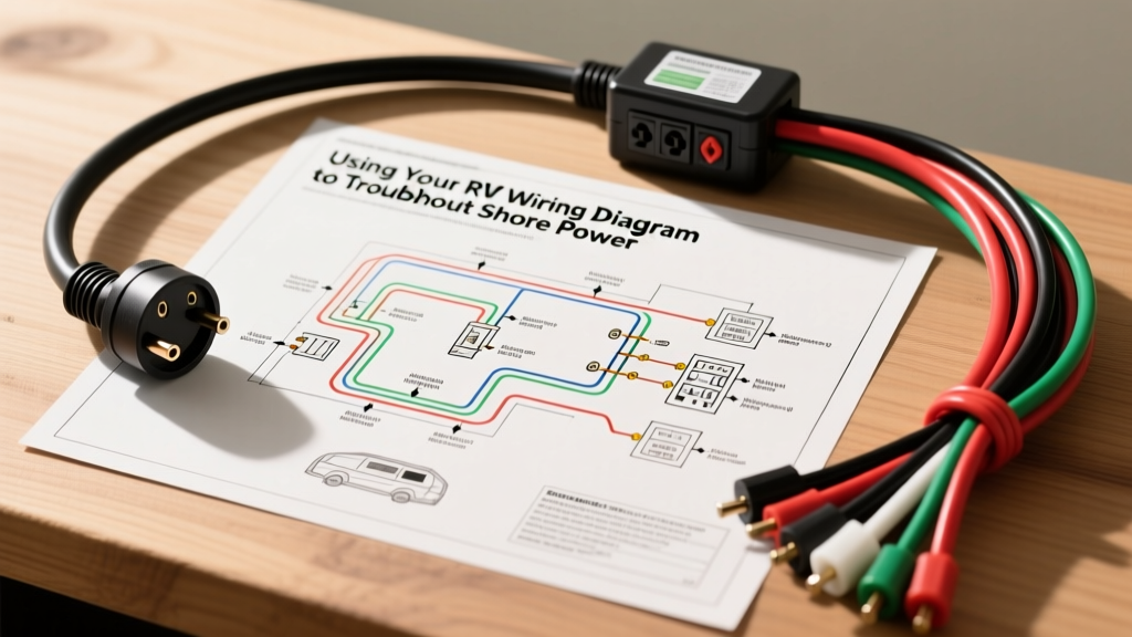
Systematic Diagnosis: Using Your RV Wiring Diagram for Shore Power Failures
When your camper loses power, guessing which wire to check is a fast track to blown fuses or damaged appliances. A factory RV wiring diagram is your most critical diagnostic tool, mapping the exact path from the shore power inlet through the main distribution panel, power converter, and 12V DC branch circuits. By following a structured, step-by-step troubleshooting flow, you can isolate whether a failure stems from a tripped AC breaker, a faulty power converter, a blown reverse-polarity fuse, or a failed battery disconnect solenoid.
This guide provides a professional-grade diagnostic sequence for 30-amp and 50-amp RV electrical systems, utilizing specific wire gauges, color codes, and multimeter testing protocols aligned with NFPA 1192 Standards for recreational vehicles.
Phase 1: Verifying the Shore Power Inlet and Main AC Lugs
Before opening the distribution panel, verify that shore power is successfully entering the RV. Failures here are often caused by melted plugs, loose terminal screws, or degraded transfer switches.
Step 1: Multimeter Testing at the Receptacle
Set your CAT III-rated digital multimeter to AC Voltage (V~). Insert the probes into the pedestal receptacle (or use a dedicated RV polarity tester) to verify the park's wiring before plugging in.
- Hot to Neutral: Should read 120V AC (±5%).
- Hot to Ground: Should read 120V AC (±5%).
- Neutral to Ground: Should read less than 2V AC. A reading higher than 2V indicates a floating neutral or high-resistance ground at the pedestal, which can destroy sensitive RV electronics.
Step 2: Inspect the Main Distribution Panel Lugs
Shut off the pedestal breaker. Remove the dead-front cover of your main AC/DC distribution panel (e.g., WFCO or Progressive Dynamics). Consult your RV wiring diagram to locate the main shore power lugs. Thermal cycling causes copper and aluminum wires to expand and contract, loosening terminal screws over time. A loose neutral wire on a 30-amp system will cause arcing, melting the insulation on the 10 AWG white wire and eventually tripping the main 30A breaker.
| Connector Type | Pins | Wire Colors (AC) | Min AWG Size | Torque Spec (Terminal) |
|---|---|---|---|---|
| NEMA TT-30 (30A) | 3 | Black (Hot), White (Neutral), Green (Ground) | 10 AWG | 45 in-lbs |
| NEMA 14-50 (50A) | 4 | Black (Hot 1), Red (Hot 2), White (Neutral), Green (Ground) | 6 AWG (or 4 AWG) | 120 in-lbs |
Source: RVIA (Recreation Vehicle Industry Association) Wiring Standards
Phase 2: Diagnosing the Power Converter (AC to DC)
If your 120V AC outlets work but your 12V DC lights, water pump, and slide-outs are dead, the issue lies within the power converter or the DC distribution block. The converter steps down 120V AC to 13.6V DC (Bulk Charge) to power 12V loads and charge the house battery.
Step 3: Check the Converter AC Input
Locate the converter's dedicated 120V AC breaker on the main panel (usually 15A or 20A). Using your multimeter, verify 120V AC at the breaker output. If voltage is present, trace the Romex (typically 14/2 or 12/2 NM-B cable) to the converter's AC input terminals. Ensure the black (hot) and white (neutral) wires are securely fastened.
Step 4: The Reverse Polarity Fuse Trap
This is the most common failure mode for DIYers and new RV owners. If the house battery was recently disconnected, replaced, or jumped, and the positive and negative cables were momentarily crossed, the reverse polarity fuses on the converter's DC output block will blow instantly to protect the unit. These are typically two 30A or 40A ATC/ATO automotive blade fuses located near the heavy-gauge DC output wires.
Consult your specific RV wiring diagram to locate the DC output block. If the 120V AC side of the converter is humming but there is 0V DC at the output terminals, pull the reverse polarity fuses and test them for continuity. Replace them with exact-match ATC fuses; never use a higher amperage fuse, as this bypasses the protection for the 6 AWG or 4 AWG DC feed wires.
Phase 3: 12V DC Distribution and Battery Disconnect Tracing
If the converter is outputting 13.6V DC, but the interior 12V fuse block shows 0V, the interruption is between the converter and the distribution panel, or at the battery disconnect solenoid.
Step 5: Bypass the Battery Disconnect Solenoid
Many modern RVs use a latching relay (solenoid) controlled by a momentary switch near the entry door. This solenoid connects the heavy 2 AWG or 4 AWG positive battery cable to the main DC fuse block. If the solenoid fails, or if the 14 AWG control circuit loses its ground, the main 12V feed is severed.
Test: Use a multimeter to check for 12V DC on the battery side of the solenoid. Then, press the interior disconnect switch and check the panel side. If voltage does not pass through when the switch clicks, the internal copper contacts of the solenoid are likely pitted or welded open. Bypass the solenoid temporarily with a heavy-gauge jumper cable to confirm the rest of the DC system functions.
Step 6: Voltage Drop Testing on Branch Circuits
If specific 12V appliances (like roof vents or slide-out motors) are underperforming, perform a voltage drop test. Place your multimeter's red probe on the positive terminal of the appliance and the black probe on the positive terminal of the DC fuse block. With the appliance running, a reading higher than 0.5V indicates high resistance in the wire run, usually due to a corroded butt splice, an undersized wire gauge, or a loose fuse connection.
Step-by-Step Troubleshooting Decision Tree
Use this logical flow to rapidly isolate your electrical fault using your RV wiring diagram:
- Symptom: Total RV Power Loss (AC and DC dead).
- Check: Shore power pedestal breaker.
- Check: Main 30A/50A RV breaker.
- Check: Transfer switch (if equipped with an onboard generator).
- Symptom: AC Works, DC is Dead.
- Check: Converter AC breaker (15A/20A).
- Check: Converter Reverse Polarity Fuses (30A/40A blades).
- Check: Battery Disconnect Solenoid engagement.
- Symptom: DC Works on Battery, Dies on Shore Power.
- Check: Converter output voltage (Should be 13.2V - 13.6V).
- Check: Auto-resetting thermal breaker on the battery positive line (often mounted 18 inches from the battery).
- Symptom: GFCI Outlets Won't Reset.
- Check: Upstream GFCI receptacle (RV bathrooms and kitchens are often daisy-chained on a single 20A breaker).
- Check: Loose neutral wire at the GFCI LINE/LOAD terminals.
Understanding RV DC Wire Color Codes
One of the most dangerous assumptions automotive technicians make when working on RVs is assuming DC wire colors match automotive standards. In standard automotive wiring, Black is ground and Red is positive. However, according to WFCO Electronics and RVIA standards, White is almost universally used as the 12V DC Negative (Ground) in RV chassis and house wiring, while Black or Red is used for 12V DC Positive. Always verify with a multimeter before cutting or splicing any wires behind an RV's DC distribution panel. Misinterpreting these colors based on automotive habits will instantly blow the converter's reverse polarity fuses and potentially fry the control boards on your RV's furnace and water heater.
Final Safety and Torque Protocols
Whenever you remove the dead-front cover of your RV's main distribution panel to trace a circuit on your RV wiring diagram, ensure the shore power cord is physically disconnected and the pedestal breaker is locked out. When re-terminating wires, always use a calibrated inch-pound torque screwdriver. Over-torquing 10 AWG stranded wire on a brass terminal block will strip the screw threads, while under-torquing will result in a high-resistance connection that generates enough heat to melt the plastic breaker housing and start an electrical fire. Adhere strictly to the manufacturer's torque specifications, typically 45 in-lbs for 10 AWG and 120 in-lbs for 6 AWG conductors.