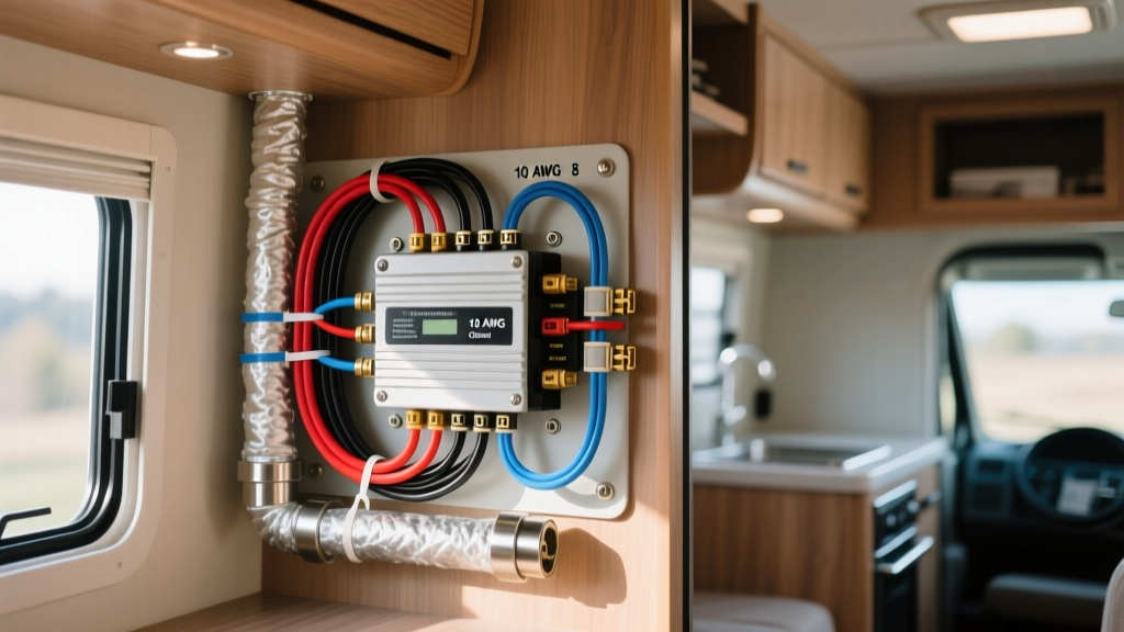
The Hidden Dangers in a Flawed Motorhome Inverter Wiring Diagram
When reviewing a motorhome inverter wiring diagram, many DIYers and even some RV technicians focus solely on making the electrical connections without understanding the underlying physics of high-current DC circuits. An inverter is not just another appliance; it is a massive continuous load that can draw hundreds of amps from your battery bank. A poorly executed installation doesn't just result in voltage drop or tripped breakers—it creates severe fire hazards, DC arc faults, and chassis electrification risks.
According to the NFPA 1192 Standard on Recreational Vehicles, electrical fires remain one of the leading causes of total-loss RV incidents. By analyzing thousands of field installations, we have identified the most frequent and dangerous deviations from proper inverter wiring schematics. Below, we break down five critical safety mistakes found in amateur and substandard motorhome inverter wiring diagrams, along with the exact specifications required to fix them.
Mistake 1: Undersizing DC Cables and Ignoring Voltage Drop
The most common error in any DIY motorhome inverter wiring diagram is using AC wiring logic for DC battery cables. A 2000W inverter operating on a 12V nominal system (which often drops to 11.5V under heavy load) will pull approximately 175A to 190A continuously. If you use 4 AWG wire for a 10-foot run, the resistance will cause a massive voltage drop, forcing the inverter to draw even more current to compensate, leading to thermal runaway and melted insulation.
You must size your cables based on the maximum continuous DC draw and the total one-way wire length (positive or negative, whichever is longer), keeping voltage drop below 3% (ideally below 1%). Furthermore, always use pure copper, fine-strand marine-grade wire (SAE J1128 or UL 1426), never copper-clad aluminum (CCA).
Inverter Cable Sizing & Overcurrent Specification Chart
| Inverter Rating | Max DC Draw (12V) | Min AWG (Up to 5 ft) | Min AWG (5 to 10 ft) | Min AWG (10 to 15 ft) | Main DC Fuse (Class T) |
|---|---|---|---|---|---|
| 1000W | 95A | 4 AWG | 2 AWG | 1/0 AWG | 110A |
| 2000W | 185A | 1/0 AWG | 2/0 AWG | 3/0 AWG | 225A |
| 3000W | 280A | 2/0 AWG | 4/0 AWG | 300 kcmil | 325A |
Mistake 2: Improper DC Overcurrent Protection Placement
A wiring diagram might show a fuse, but it rarely emphasizes placement. The Victron Energy Wiring Unlimited Guide and ABYC E-11 standards strictly dictate that the main DC overcurrent protection device (OCPD) must be installed as close to the battery positive terminal as possible—specifically within 7 inches of the terminal. If the wire is enclosed in a continuous protective sheath, this distance can be extended to 72 inches, but the 7-inch rule is the gold standard for exposed RV battery bays.
The AIC Trap: Many diagrams call for standard ANL fuses. However, if you are wiring a modern motorhome with a large lithium iron phosphate (LiFePO4) battery bank capable of delivering 1000+ amps of short-circuit current, a standard ANL fuse (typically rated for 2,000 AIC) may violently explode before it can clear the fault. You must specify a Class T fuse, which boasts a 20,000 Ampere Interrupting Capacity (AIC), ensuring it safely extinguishes the DC arc during a dead short.
Mistake 3: Neutral-to-Ground Bonding Conflicts
When integrating an inverter/charger into an RV's AC distribution panel, the Neutral-to-Ground (N-G) bond is a frequent source of GFCI tripping and chassis shock hazards. In a standard 50-amp or 30-amp shore power setup, the N-G bond occurs at the main distribution panel. However, many modern pure sine wave inverters feature an internal transfer switch and an internal N-G bonding relay.
If your motorhome inverter wiring diagram connects the inverter's AC output to a subpanel that already has a hardwired N-G bond, and the inverter also activates its internal bond relay when inverting, you create a parallel neutral path. This means neutral current will flow back to the battery negative bus via the chassis ground wire.
How to Verify and Correct N-G Bonding:
- Disconnect all power: Unplug shore power, turn off the generator, and disconnect the main battery positive.
- Set Inverter to 'Invert' Mode: Force the inverter to create its own AC power.
- Multimeter Test: Measure the resistance between the AC Neutral bus bar and the AC Ground bus bar in the inverter's dedicated subpanel. It should read near 0 ohms (bonded).
- Check the Main Panel: Measure Neutral to Ground at the main RV panel. It should read infinite resistance (open) while the inverter is powering the system, proving the inverter's internal relay is handling the bond and the main panel's bond is isolated via the transfer switch.
Mistake 4: High-Resistance Chassis Grounding
In a 12V DC system, the ground return path must be treated with the exact same respect as the positive supply path. A massive mistake is using a small 8 AWG wire to ground a 3000W inverter to the chassis, or bolting a massive 2/0 AWG ground lug to a painted or powder-coated frame rail.
The negative battery cable and the inverter ground cable must be the exact same AWG. When terminating to the chassis:
- Surface Prep: Use a rotary wire brush to remove paint, zinc plating, and rust down to bare, shiny steel. Do not rely on a lock washer to bite through powder coating.
- Hardware: Use a Grade 8 or stainless steel bolt with a hardened flat washer and a star lock washer.
- Torque Specs: A 5/16' bolt securing a 2/0 AWG lug must be torqued to 10-12 ft-lbs (13.5-16 Nm). A 3/8' bolt requires 15-18 ft-lbs (20-24 Nm).
- Corrosion Protection: Only apply dielectric grease or liquid electrical tape after the connection has been fully torqued and inspected. Applying it before will result in a high-resistance connection.
Mistake 5: Ignoring AC Wire Routing and EMI Interference
Electromagnetic Interference (EMI) is rarely considered in basic motorhome inverter wiring diagrams. Running 120V AC inverter output wires parallel and tightly bundled with 12V DC communication wires (like RS-485, CAN bus, or thermostat wires) will induce voltage spikes that can destroy sensitive RV control boards and cause erratic inverter behavior.
According to the Magnum Energy ME Series Inverter Installation Manual, AC and DC wiring must be separated. If they must cross, they should cross at a strict 90-degree angle. If they must run parallel, maintain a minimum separation distance of 2 inches (5 cm), or route the AC wires through a grounded metallic flexible conduit to contain the electromagnetic field.
Pre-Energization Safety Checklist
Before flipping the DC breaker or reconnecting the battery negative terminal, run through this mandatory verification checklist to ensure your wiring diagram was executed flawlessly:
- Pull Test: Give every crimped lug a firm physical tug. A properly crimped 2/0 AWG lug using a 12-ton hydraulic crimper with a hexagonal die will not pull off, even with extreme force. Never use a hammer and chisel to crimp battery lugs.
- Heat Shrink Verification: Ensure all DC lugs are sealed with 3:1 adhesive-lined marine heat shrink. The adhesive should be visibly oozing from the edges, preventing moisture wicking into the copper strands.
- Polarity Check: Use a multimeter to verify DC polarity at the inverter's DC input terminals before tightening the final connection. A reversed polarity mistake will instantly destroy the inverter's internal MOSFETs, even if the main fuse hasn't blown yet.
- AC Voltage Verification: With the inverter running and no load applied, measure the AC output at the inverter terminals. You should see 115V-120V AC. Measure Hot-to-Ground and Neutral-to-Ground to ensure there are no floating grounds or crossed wires in the subpanel.
By respecting the physics of high-amperage DC circuits and adhering strictly to NFPA and ABYC standards, your motorhome inverter installation will be safe, efficient, and capable of handling the rigorous demands of full-time boondocking.