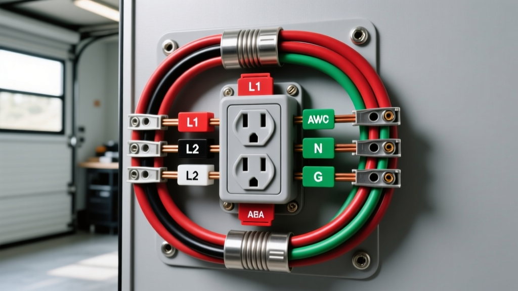
Understanding the 50 Amp RV Electrical System
When transitioning from a standard 30-amp camper setup to a larger fifth wheel or motorhome, deciphering a 50 amp RV wiring diagram is your first critical step. Unlike a 30-amp system, which provides a single 120V hot leg, a 50-amp RV service is vastly more robust. It is designed to simultaneously power multiple high-draw appliances like dual roof air conditioners, residential refrigerators, and electric water heaters without tripping the main pedestal breaker.
For beginners, the most important concept to grasp is that a 50-amp RV service is actually a 120/240V split-phase system. However, your RV’s internal wiring diagram does not utilize the 240V potential. Instead, the RV's main distribution panel splits the incoming power into two separate 120V, 50-amp circuits (often labeled as Leg 1 and Leg 2). This gives you a total of 100 amps of usable 120V power, distributed across your camper's appliances.
The Split-Phase Secret: NEMA 14-50R and TT-50P Pinouts
The standard shore power receptacle you will encounter at RV parks is the NEMA 14-50R. The corresponding plug on your RV's power cord is the TT-50P (Travel Trailer 50-amp Plug). While they share the same electrical characteristics, the TT-50P features an angled neutral pin to prevent accidental insertion into non-RV 240V receptacles (like those used for arc welders).
Below is the definitive pinout configuration for your 50 amp RV wiring diagram. Memorizing these four connection points is essential for troubleshooting and safe cord replacement.
| Pin Designation | Function | Standard Wire Color | Voltage Potential | Max Amperage |
|---|---|---|---|---|
| X (Hot 1) | Line 1 (120V AC) | Black | 120V to Neutral | 50 Amps |
| Y (Hot 2) | Line 2 (120V AC) | Red | 120V to Neutral | 50 Amps |
| W (Neutral) | Return Path | White | 0V (Reference) | 50 Amps* |
| G (Ground) | Safety Shield | Green | 0V (Earth) | Fault Path Only |
*Note: In a perfectly balanced split-phase system, the neutral carries 0 amps. In a worst-case unbalanced scenario (e.g., Leg 1 draws 50A, Leg 2 draws 0A), the neutral carries a maximum of 50 amps, not 100 amps.
Wire Gauge and Cable Specifications
A common beginner mistake is attempting to wire a 50-amp RV circuit using undersized cable, which leads to severe voltage drop, melted insulation, and potential fire hazards. According to the National Electrical Code (NFPA 70), wire ampacity must be matched to the breaker size and the cable's thermal rating.
For a flexible, detachable RV power cord (rated for 600V), you must use specific jacketed cables designed for hard service and outdoor exposure.
| Conductor Material | Required AWG Size | Cable Jacket Type | Stranding Class |
|---|---|---|---|
| Copper | 6 AWG (4-Conductor) | SOOW, STW, or SEOW | Class K or L (Fine) |
| Aluminum | 4 AWG (4-Conductor) | SOOW or STW | Class B or C |
Always opt for copper 6 AWG, 4-conductor cable (Black, Red, White, Green). Copper offers superior conductivity, better resistance to vibration-induced strand breakage, and easier termination at the TT-50P plug head compared to aluminum.
Step-by-Step: Wiring a TT-50P Replacement Plug Head
If your RV's power cord shows signs of thermal damage, melting, or exposed copper near the plug head, immediate replacement is required. The RV Industry Association (RVIA) strictly mandates that all shore power connections maintain secure, low-resistance terminations to prevent arcing.
- Cut and Strip: Cut off the damaged TT-50P plug head. Strip back 3 inches of the heavy SOOW outer jacket. Be extremely careful not to nick the insulation of the four internal 6 AWG conductors.
- Prepare the Conductors: Strip exactly 3/4 inch of insulation from the Black, Red, White, and Green wires. Do not twist the fine copper strands too tightly; keep them bundled but natural to ensure maximum surface contact inside the terminal.
- Route the Strain Relief: Thread the cable through the plug's rear housing and the rubber strain relief clamp. This clamp must bite down on the thick outer SOOW jacket, never on the individual colored wires.
- Terminate the Wires:
- Insert the Black wire into the X (Brass) terminal.
- Insert the Red wire into the Y (Brass) terminal.
- Insert the White wire into the W (Silver/Chrome) terminal. (Note: The W terminal corresponds to the angled, oversized pin).
- Insert the Green wire into the G (Green) grounding screw.
- Torque to Spec: Using a calibrated torque screwdriver, tighten the terminal screws to 45 in-lbs (or the manufacturer's specific rating). Under-torquing causes resistance and heat; over-torquing crushes the copper strands and creates a weak point.
- Inspect for Whiskers: Ensure no stray copper "whiskers" are protruding from the terminals. A single stray strand bridging the gap between Hot and Neutral will cause a catastrophic dead short when plugged in.
Tracing the Diagram: Inside the RV Distribution Panel
Once power leaves the TT-50P plug and travels through the 6 AWG cord, it enters the RV's main AC distribution panel. Understanding this portion of the 50 amp RV wiring diagram is crucial for diagnosing interior power losses.
The incoming Black (L1) and Red (L2) wires land on a 2-pole 50-amp main breaker. While this breaker looks like a residential 240V breaker, the RV panel's internal bus bar is configured differently. The bus bar splits L1 and L2 into two distinct 120V legs. From here, individual 15A and 20A branch circuit breakers are alternated between Leg 1 and Leg 2 to balance the electrical load. For example, the living room AC might be on Leg 1, while the bedroom AC and microwave are on Leg 2.
The White (Neutral) wire connects directly to the isolated neutral bus bar, and the Green (Ground) wire connects to the grounded chassis bus bar. These two bars must never be bonded together inside the RV sub-panel; bonding only occurs at the shore power pedestal or generator source.
Common Beginner Mistakes and Troubleshooting
Even with a perfect wiring diagram, real-world RV parks present severe electrical hazards. Here is how to identify and protect against common 50-amp pedestal failures:
- Lost Leg (Open Hot): If the pedestal's X or Y terminal is dead, exactly half of your RV will lose power. Your main panel will show 120V on one leg and 0V on the other. This is a park-side issue requiring the camp host to replace the pedestal breaker.
- Open Neutral: This is the most dangerous fault. If the White wire connection fails at the pedestal, the 120V appliances on Leg 1 and Leg 2 will effectively become wired in series across 240V. This will instantly destroy sensitive electronics, microwaves, and TV power supplies.
- Reversed Polarity: Occurs when a DIY electrician wires the Hot and Neutral backward at the campsite pedestal. Your RV will appear to function normally, but the chassis could become energized if an internal fault occurs.
The Ultimate Defense: Install an EMS
Because you cannot trust the wiring diagram of the campsite pedestal you plug into, the Progressive Industries Electrical Management System (EMS) is a mandatory upgrade for 50-amp RVers. Hardwired directly into your RV's main power cord entry point, a 50-amp EMS monitors voltage, frequency, and polarity on both L1 and L2. If it detects an open neutral, reverse polarity, or voltage dropping below 104V / spiking above 132V, the internal contactor physically severs the connection, saving your RV's appliances from thousands of dollars in damage.
Final Thoughts on 50 Amp Safety
Mastering your 50 amp RV wiring diagram empowers you to safely maintain your rig, replace damaged cord ends, and understand exactly how your appliances draw power. Always respect the immense current capacity of a 50-amp split-phase system. Use properly rated 6 AWG copper cables, torque all connections to specification, and never bypass safety protocols when connecting to shore power.