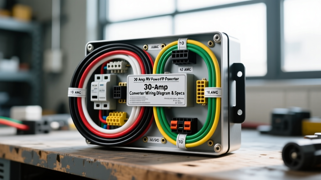
30 Amp RV Power Converter Architecture & System Overview
Understanding the 30 amp RV power converter wiring diagram requires a clear distinction between the 120V AC shore power distribution and the 12V DC load center. In a standard 30-amp recreational vehicle, the power converter (often rated between 45A and 65A DC output, such as the WFCO 8955 or Progressive Dynamics PD4650) acts as the bridge between these two systems. It steps down 120V AC from the shore power pedestal to 13.6V DC to power interior lighting, water pumps, and slide-out motors, while simultaneously providing a multi-stage charge profile to the deep-cycle battery bank.
This technical reference details the exact wire gauges, National Electrical Code (NEC) color standards, branch circuit breaker sizing, and terminal torque specifications required for a safe, code-compliant converter installation. Improper wiring in the AC input or DC output stages is the leading cause of converter thermal failure and 12V system voltage drop.
NEMA TT-30 Shore Power Input & Main AC Distribution
The 30-amp RV system utilizes a NEMA TT-30P plug mating with a TT-30R receptacle. Unlike a 50-amp NEMA 14-50R which provides split-phase 240V, the TT-30 is strictly a 120V single-phase system. The main service cord enters the RV's main AC distribution panel, which houses the 30A main breaker and individual branch breakers.
30A AC Wire Gauge & Color Code Reference
| Circuit Segment | Wire Gauge (AWG) | Insulation Color | Breaker Size | Terminal Torque |
|---|---|---|---|---|
| Shore Cord to Main Lug | 10 AWG Stranded | Black (Hot), White (Neutral), Green (Ground) | 30A HACR Main | 40 in-lbs |
| Branch: AC Receptacles | 12 AWG Stranded | Black, White, Bare Copper | 20A GFCI/AFCI | 35 in-lbs |
| Branch: Air Conditioner | 10 AWG Stranded | Black, White, Bare Copper | 30A HACR | 40 in-lbs |
According to NFPA 70 (NEC) Article 551, all 10 AWG conductors terminating in the main panel must be stripped exactly 3/8 inch to prevent exposed copper from causing short circuits against the panel chassis, while ensuring the wire clamp secures the copper strands and not the insulation.
Power Converter AC Input Wiring (The Branch Circuit Misconception)
A critical error found in many DIY 30 amp RV power converter wiring diagrams is connecting the converter's AC input directly to the 30A main breaker lugs. The converter is a load on the AC system, not a main service disconnect. It must be wired to a dedicated branch circuit breaker inside the AC distribution panel.
Sizing the Converter AC Branch Breaker
To determine the correct AC branch breaker and wire gauge, calculate the AC input draw of the converter. A 55-amp DC output converter operating at 13.6V DC outputs roughly 748 watts. Accounting for an 80% power factor and conversion efficiency, the AC input draw is approximately 9.5 amps at 120V AC.
- 15A Branch Breaker: Requires 14 AWG stranded copper wire (Black, White, Green).
- 20A Branch Breaker: Requires 12 AWG stranded copper wire (Black, White, Green). This is the industry standard for modern 55A+ converters to accommodate initial inrush currents and prevent nuisance tripping.
Expert Note: Never use 10 AWG wire on a converter AC input terminal block unless explicitly specified by the manufacturer. Most converter terminal blocks are rated for 14-12 AWG. Forcing 10 AWG wire into these terminals can strip the terminal screws or crack the phenolic block, creating a high-resistance arc fault hazard.
Converter DC Output & 12V Distribution Wiring Specs
The DC output stage of the power converter handles high continuous amperage, making voltage drop and thermal management the primary engineering concerns. The DC wires route from the converter's output terminals to the DC fuse distribution board, and subsequently to the battery bank via a battery disconnect switch and overcurrent protection.
DC Output Wire Sizing & Voltage Drop
Undersized DC wiring causes a voltage drop between the converter and the battery. If the converter senses less than 13.2V at its output terminals due to wire resistance, it may falsely remain in 'Bulk' charge mode indefinitely, boiling the battery electrolyte. The RV Industry Association (RVIA) and ABYC standards recommend keeping DC voltage drop below 3% for charging circuits.
| Converter DC Rating | One-Way Wire Distance | Required AWG (Copper) | Max Voltage Drop (3%) |
|---|---|---|---|
| 45 Amp | Under 10 Feet | 8 AWG | 0.36V |
| 45 Amp | 10 to 15 Feet | 6 AWG | 0.30V |
| 55 - 60 Amp | Under 10 Feet | 6 AWG | 0.44V |
| 55 - 60 Amp | 10 to 20 Feet | 4 AWG | 0.35V |
For DC wiring, the standard RV color code dictates Red for positive (+) and White (or sometimes Black) for negative (-). Always use SAE J1128 compliant stranded copper wire with a temperature rating of at least 105°C for engine bay or high-heat compartment routing.
Terminal Torque & Termination Specifications
Loose connections on the DC output terminals create resistance, leading to localized heating and melted terminal blocks. Use a calibrated inch-pound torque screwdriver to secure all converter and bus bar connections.
- 14-12 AWG (AC Branch Input): 35 in-lbs
- 10 AWG (AC Main / DC Low Amp): 40 in-lbs
- 8-6 AWG (DC Output High Amp): 50 in-lbs
- 4-2 AWG (Battery Bus / Inverter): 120 in-lbs (10 ft-lbs)
Always apply an anti-oxidant compound (such as Noalox) to aluminum lugs if your DC bus bar utilizes aluminum terminals rather than tin-plated copper. Copper-to-copper connections do not strictly require it, but it prevents galvanic corrosion in high-humidity RV environments.
Battery Disconnect Switch & Reverse Polarity Protection
A proper 30 amp RV power converter wiring diagram must integrate a battery disconnect switch and reverse polarity fuses to protect the converter's internal diodes and the RV's 12V appliances.
Correct Placement of the Battery Disconnect
The 12V battery disconnect switch must be installed on the load side of the DC distribution board, between the fuse panel and the 12V appliances. Never install the main battery disconnect between the power converter and the battery bank. If the converter is powered on while the battery is disconnected via a series switch, the converter loses its battery 'buffer'. Without a battery to stabilize the voltage, the converter's output can spike to 16V+ during load dumps, instantly destroying 12V control boards on refrigerators, furnaces, and water heaters.
Reverse Polarity Fuses
Located on the DC fuse board, reverse polarity fuses (typically 30A or 40A automotive blade fuses) protect the converter if the battery is wired backward. If a converter is outputting 13.6V DC but the RV has zero 12V power, check these specific fuses first. A blown reverse polarity fuse almost always indicates a shorted wire on the chassis or a battery installed with swapped positive/negative terminals.
Common Failure Modes & Diagnostic Voltage Drops
When troubleshooting a 30-amp RV electrical system, use a digital multimeter (DMM) to perform a voltage drop test across the converter connections. A healthy connection should show a voltage drop of less than 0.1V under load.
- Symptom: Converter fan runs continuously, battery fails to charge past 12.2V.
Cause: High resistance on the DC negative (White) wire ground path. The converter cannot accurately sense battery voltage.
Fix: Clean the chassis ground ring terminal, sand away paint/rust, and retorque to 50 in-lbs. - Symptom: AC branch breaker trips immediately when shore power is connected.
Cause: Failed internal AC varistor or shorted step-down transformer winding inside the converter due to a brownout or lightning surge.
Fix: Disconnect the AC branch input wire from the converter. If the breaker holds, the converter requires replacement. - Symptom: 12V lights pulse or flicker when the water pump engages.
Cause: Undersized DC output wiring from the converter to the bus bar, or a failing battery with high internal resistance unable to buffer the pump's inrush current.
Fix: Upgrade DC output wiring to 4 AWG and load-test the deep cycle battery.
By adhering strictly to these wire gauges, breaker sizing rules, and torque specifications, you ensure the longevity of the RV's power converter and the safety of the entire 30-amp electrical ecosystem.