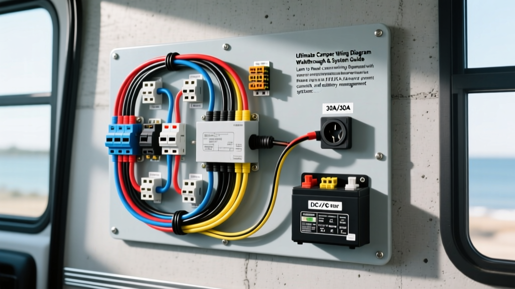
Decoding the Factory Camper Wiring Diagram
When you unroll a factory camper wiring diagram, the sheer density of intersecting lines, node numbers, and component symbols can be overwhelming. Unlike standard automotive chassis wiring, recreational vehicles operate as dual-voltage micro-grids. They must seamlessly integrate 120V AC shore power, 12V DC battery systems, and high-amperage inverter circuits. According to the RV Industry Association (RVIA), all modern campers must adhere to NFPA 1192 standards, which dictate strict wire color codes, overcurrent protection, and grounding protocols. This comprehensive walkthrough dissects the primary nodes of a standard travel trailer or fifth-wheel electrical schematic, providing the technical depth required for troubleshooting, upgrades, and repairs.
Phase 1: AC Shore Power Inlet & Main Distribution
The AC side of your camper wiring diagram begins at the exterior shore power inlet and terminates at the main AC breaker panel. The configuration depends entirely on whether your rig is equipped with a 30-amp or 50-amp service.
30-Amp Service (NEMA TT-30)
A 30-amp system provides 120V AC. The diagram will show a 3-prong inlet (Hot, Neutral, Ground). The main feed wire is typically 10 AWG THHN/THWN-2 stranded copper. In the RVIA color code standard, the Hot line is Black, Neutral is White, and Ground is Green (or bare copper). This single 120V leg feeds a 30A main breaker, which then distributes power to branch circuits (A/C unit, microwave, outlets) via 15A or 20A branch breakers using 14 AWG or 12 AWG romex-style wiring.
50-Amp Service (NEMA 14-50R)
A 50-amp diagram reveals a 4-prong inlet delivering two 120V AC legs (L1 and L2) for a total of 240V potential, though RV appliances utilize the 120V split-phase configuration. The main feed requires heavy 6 AWG (or 4 AWG for runs exceeding 40 feet) 4-conductor cable. Pin 1 (X) is Black (L1), Pin 2 (Y) is Red (L2), Pin 3 (W) is White (Neutral), and Pin 4 (G) is Green (Ground). The main breaker panel will feature a dual 50A breaker, distributing L1 and L2 across separate bus bars to balance the electrical load.
Phase 2: The Converter/Charger Nexus
The heart of the dual-voltage system is the power converter (e.g., WFCO, Progressive Dynamics, or Iota). On your camper wiring diagram, the converter acts as the bridge between the AC breaker panel and the 12V DC fuse panel.
- AC Input: Fed by a dedicated 15A or 20A breaker on the AC panel using 12 AWG or 14 AWG solid/stranded wire.
- DC Output: Steps 120V AC down to 13.6V DC (bulk charge) and up to 14.4V DC (absorption). The output cables are heavy-gauge stranded wire (typically 6 AWG or 4 AWG) routed directly to the DC distribution bus and battery bank.
- Reverse Polarity Fuses: The diagram will explicitly show 30A or 40A SAE J1284 blade fuses on the positive DC output line. These protect the converter's internal diodes from catastrophic failure if the battery cables are accidentally reversed during maintenance.
Pro Tip: When tracing converter wiring on a schematic, look for the "Charge Line" relay. Many modern diagrams include a battery disconnect solenoid (often a Trombetta or White-Rodgers continuous duty relay) that physically isolates the converter from the house batteries when the storage switch is engaged.
Phase 3: 12V DC Distribution & Appliance Circuits
The 12V DC section of the camper wiring diagram governs lighting, water pumps, slide-out motors, and control boards for gas appliances. A critical distinction for automotive technicians transitioning to RVs is the RVIA DC color code: White is frequently used as the 12V DC Ground, while Black or Red is 12V DC Positive. This is the exact opposite of standard automotive chassis wiring and a common source of short-circuit disasters.
Sizing DC Wiring for Voltage Drop
Unlike AC circuits where breaker sizing dictates wire gauge, 12V DC circuits must be sized based on voltage drop over distance. A 12V water pump drawing 10 amps located 25 feet from the fuse panel requires thicker wire than a 10-amp interior light located 5 feet away. The Progressive Dynamics technical portal recommends keeping voltage drop below 3% for sensitive RV electronics like inverter control boards and refrigerator logic modules.
| Wire Gauge (AWG) | Max Amperage (Chassis) | Max Run Length (10A Load @ 3% Drop) | Common RV Application |
|---|---|---|---|
| 14 AWG | 15A | 11 feet | Interior LED lighting, 12V USB ports |
| 12 AWG | 20A | 18 feet | Water pump, 12V ventilation fans |
| 10 AWG | 30A | 29 feet | Refrigerator 12V heating element, awning motor |
| 8 AWG | 40A | 46 feet | Slide-out motors, electric tongue jack |
| 6 AWG | 60A | 73 feet | Converter DC output, main battery feed |
Phase 4: High-Current DC Appliances & Motor Circuits
Slide-out motors, hydraulic leveling jacks, and electric trailer brakes represent the highest DC current draws on the diagram. These circuits bypass the standard 12V fuse block entirely, utilizing standalone MAXI fuses or DC circuit breakers (e.g., 30A to 50A Bussmann auto-reset breakers) mounted directly within 18 inches of the battery positive terminal, per NFPA 1192 guidelines.
When tracing slide-out wiring on a schematic, you will notice a DPDT (Double Pole, Double Throw) momentary toggle switch. This switch reverses the polarity to the 12V motor to extend and retract the room. The ground path for these motors is often achieved through the steel chassis frame rather than a dedicated ground wire back to the battery. If your diagram shows a dedicated ground wire but the physical motor relies on chassis grounding, you are likely dealing with a manufacturer mid-year production change or an aftermarket dealer modification.
Troubleshooting Diagram-to-Reality Deviations
Factory camper wiring diagrams represent the ideal build state. In reality, RV manufacturing involves significant manual assembly, leading to common deviations that frustrate technicians:
- The "White Wire" Mystery: While RVIA mandates white for DC ground, some sub-contractors use white for 12V positive on specific appliance pigtails (like Dometic refrigerators) due to automotive harness sourcing. Always verify with a multimeter before cutting.
- Shared Neutral Faults: On 50-amp diagrams, L1 and L2 branch circuits must have isolated neutrals. A common factory error is daisy-chaining the neutral wire from a microwave on L1 to a GFCI outlet on L2. This causes immediate tripping of GFCI or AFCI breakers due to unbalanced current return.
- Terminal Torque Failures: Schematics do not show torque specs. The #1 cause of melted converter bus bars and shore power inlet burns is under-torqued set screws. 6 AWG copper under a main breaker lug requires approximately 45 in-lbs of torque. Vibration from highway travel loosens poorly torqued connections, increasing resistance and generating catastrophic heat.
Mastering the camper wiring diagram requires treating it as a foundational map, not an absolute truth. Always pair your schematic reading with physical continuity testing and voltage drop analysis to ensure your RV's electrical micro-grid operates safely and efficiently.