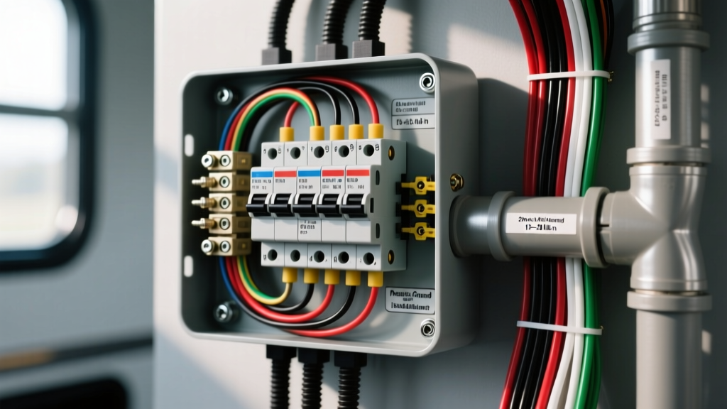
Introduction to 30A RV Subpanel Architecture
When analyzing a 30 amp RV breaker box wiring diagram, it is critical to understand that an RV electrical distribution panel is fundamentally a subpanel, not a main service panel. Unlike residential main panels where the neutral and ground bus bars are bonded together, RV electrical systems must maintain strict isolation between the grounded (neutral) conductor and the grounding (chassis) conductor. This distinction is the cornerstone of RV electrical safety and is heavily regulated by both the NFPA 70 National Electrical Code (NEC) Article 551 and the NFPA 1192 Standard on Recreational Vehicles.
A 30-amp RV system operates on a 120-volt, single-phase, 3-wire configuration supplied via a NEMA TT-30R receptacle. The maximum continuous load should not exceed 80 percent of the breaker rating, meaning your total simultaneous AC appliance draw should remain below 24 amps (2,880 watts). This advanced guide deconstructs the wiring diagram, termination specifications, and critical failure modes inherent to 30A camper electrical systems.
Decoding the 30 Amp RV Breaker Box Wiring Diagram
The physical routing of a 30A RV breaker box follows a strict hierarchy from the shore power inlet to the branch circuits. The incoming feed originates at the TT-30P plug, travels through a heavy-duty 10 AWG SOOW or STOW flexible cord, and terminates at a main disconnect or directly into the main lugs of the RV subpanel.
Incoming Feed and Main Lugs
The main hot lug receives the 10 AWG black wire, the neutral lug receives the 10 AWG white wire, and the ground bus receives the 10 AWG green or bare copper wire. In high-end fifth wheels and motorhomes, you will often find a 30-amp main disconnect breaker positioned before the branch circuit bus bars. In smaller travel trailers, the main lugs feed the bus bars directly, relying on the pedestal breaker at the campground for primary overcurrent protection. Proper wire preparation is vital: strip exactly 3/8 inch to 1/2 inch of insulation, ensuring no bare copper is exposed outside the terminal clamp, and no insulation is trapped inside the clamp.
Branch Circuit Breaker Mapping
Branch circuits in a 30-amp RV are typically divided into dedicated appliance circuits and general-purpose receptacle circuits. The diagram below illustrates standard branch circuit mapping, wire sizing, and breaker selection.
| Circuit Designation | Breaker Size | Wire Gauge (THHN/NM-B) | Breaker Type Requirement |
|---|---|---|---|
| Air Conditioner (15k BTU) | 20 Amp | 12 AWG | HACR Rated |
| Power Converter / Charger | 15 Amp or 20 Amp | 14 AWG or 12 AWG | Standard Thermal-Magnetic |
| Water Heater (AC Element) | 15 Amp | 14 AWG | Standard Thermal-Magnetic |
| Microwave / Refrigerator | 20 Amp | 12 AWG | Standard Thermal-Magnetic |
| General Receptacles (GFCI) | 15 Amp or 20 Amp | 14 AWG or 12 AWG | Standard Thermal-Magnetic |
Note the requirement for HACR (Heating, Air Conditioning, and Refrigeration) rated breakers for the rooftop AC unit. HVAC compressors generate massive inrush currents (Locked Rotor Amps) that can trip standard thermal-magnetic breakers prematurely. HACR breakers feature modified magnetic trip curves designed to withstand these momentary surges.
Critical Code Deviations: Neutral vs. Ground Isolation
The most lethal mistake made by DIYers modifying a 30 amp RV breaker box wiring diagram is bonding the neutral bus bar to the ground bus bar or the panel chassis. In a residential main panel, this bond is required. In an RV subpanel, it is strictly prohibited by the RV Industry Association (RVIA) Standards and NEC Article 551.
If the neutral and ground are bonded inside the RV breaker box, a portion of the 120V return current will flow backward through the RV chassis and the shore power ground wire. If the campground pedestal ground pin is compromised, corroded, or severed, the entire aluminum or fiberglass exterior skin of the RV becomes energized at 120 volts. This phenomenon, known as 'Hot Skin,' can cause fatal electrocution when a person touches the RV while standing on the ground. Always verify that the neutral bus bar is mounted on isolated standoffs and has zero continuity to the panel chassis.
Converter and Charger Integration Circuit
The power converter is the bridge between the 120V AC breaker box and the 12V DC fuse board. On the AC wiring diagram, the converter is fed by a dedicated 15A or 20A breaker. The 120V AC wiring (Black, White, Green) terminates in the converter AC junction box. Internally, the converter rectifies this AC power to 13.6V DC to power the camper DC loads and charge the house battery bank.
When wiring the DC side of the converter to the battery bank and DC fuse board, you must transition to DC wire color codes. According to SAE J1128 and ABYC E-11 standards, the positive DC feed should be red or yellow, and the negative DC return should be black or white. Because DC current is significantly higher than AC current for the same wattage, the DC cables must be heavily oversized. A 60-amp converter requires a minimum of 6 AWG stranded copper wire for runs up to 10 feet, and 4 AWG for runs up to 15 feet, to maintain a voltage drop below 3 percent.
Advanced Termination and Torque Specifications
Thermal failure at breaker terminals is a leading cause of RV electrical fires. Vibration from highway travel and thermal expansion from high-draw appliances like air conditioners cause terminal screws to back out over time. A loose connection increases electrical resistance, generating intense localized heat that melts the breaker casing and bus bar insulation. Use a calibrated inch-pound torque screwdriver to terminate all connections according to the manufacturer specifications.
| Termination Point | Wire Size | Torque Specification | Strip Length |
|---|---|---|---|
| Main Panel Lugs (e.g., Square D HOM) | 10 AWG Stranded | 35 in-lbs | 3/8 inch |
| Branch Breaker Terminal (15A/20A) | 12 or 14 AWG Solid | 12 to 15 in-lbs | 1/2 inch |
| Neutral / Ground Bus Bars | 10 to 14 AWG | 20 to 25 in-lbs | 3/8 inch |
Advanced Troubleshooting and Thermal Failure Modes
When diagnosing voltage drops or intermittent power loss in a 30-amp RV system, do not rely solely on a standard digital multimeter. A multimeter will read 120V on a circuit with a failing, high-resistance connection as long as there is no load applied. The moment an appliance draws current, the voltage will collapse.
Instead, utilize a thermal imaging camera (FLIR) while the RV is under a sustained load (e.g., AC compressor running, water heater element engaged). Scan the breaker box for thermal anomalies. A healthy breaker terminal should be within 5 to 10 degrees Fahrenheit of the ambient panel temperature. A terminal showing a delta-T of 30 degrees or higher indicates a failing mechanical connection, oxidation on the bus bar, or a fatigued breaker internal bimetallic strip. Additionally, inspect the neutral bus bar for 'harmonic heating.' In RV parks with heavy non-linear loads (like cheap LED drivers and inverter chargers), the neutral bus can overheat even if the hot legs are well within their ampacity limits. Ensure all neutral set-screws are torqued to spec and that no more than one neutral wire is terminated under a single set-screw, a common code violation that leads to arcing and neutral burnout.