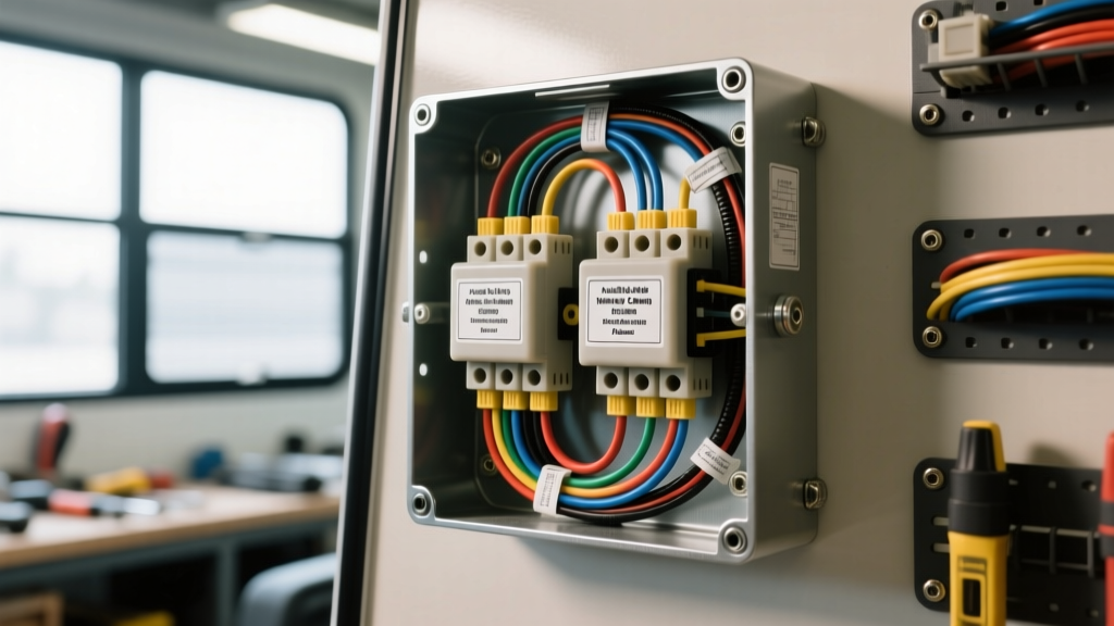
The Hidden Dangers in 30 Amp Camper Wiring Diagrams
Interpreting a 30 amp camper wiring diagram seems straightforward to seasoned electricians, but the unique environment of a recreational vehicle introduces variables that standard residential wiring does not. An RV is essentially a mobile subpanel subjected to constant vibration, extreme temperature fluctuations, and varying shore power qualities. A single misinterpreted line on a schematic or a swapped wire at the main distribution panel can result in catastrophic converter failure, melted insulation, or lethal chassis electrification.
According to NFPA 70 (NEC) Article 551, which governs Recreational Vehicles and Recreational Vehicle Parks, the grounding and bonding requirements for RVs are strictly defined to prevent parallel neutral paths. Yet, DIYers and even some aftermarket technicians routinely violate these codes. Below, we dissect the most critical mistakes made when wiring or troubleshooting a 30-amp RV electrical system and provide the exact specifications needed to ensure your rig remains safe and operational.
NEMA TT-30 Pinout Confusion: The 125V vs. 240V Trap
The most dangerous mistake involving a 30 amp camper wiring diagram is confusing the NEMA TT-30 (Travel Trailer 30-Amp) configuration with standard residential 30-amp configurations like the NEMA 10-30 or 14-30 (used for electric dryers).
- NEMA TT-30P/R: 125V AC, 30A max. Pins: X (Hot/Brass), W (Neutral/Silver), Y (Ground/Green).
- NEMA 10-30 / 14-30: 125/250V AC. Pins include two hot legs (X and Y) and a neutral or ground.
The Hazard: Campers frequently purchase cheap 'Dryer to RV' adapters to plug into a home garage outlet. If the home outlet is wired for 240V, the adapter will feed 240V directly into the RV's 125V neutral bus. This instantly bypasses the main 30A breaker's over-current protection (since the voltage is high, not the amperage) and will violently destroy the AC-to-DC converter, microwave control boards, and air conditioning capacitors. Always verify the source voltage with a multimeter before connecting.
Top 5 Fatal Mistakes When Reading a 30 Amp Camper Wiring Diagram
Mistake 1: Bonding Neutral to Ground in the RV Subpanel
In a standard residential main panel, the neutral and ground buses are bonded. However, an RV is a subpanel. According to RVIA ANSI/RVIA LV standards, the neutral and ground must remain strictly isolated within the camper's main distribution panel. If you bond them inside the RV, any fault current returning on the neutral will also travel through the grounding wire and the RV's metal chassis. If the shore power ground fails, anyone touching the exterior of the camper while standing on damp earth can become the path to ground, resulting in a lethal shock.
Mistake 2: Undersizing the Main AC Feeder Wire
A common error when replacing a main shore power cord or rewiring the inlet to the breaker panel is using 12 AWG wire because it is rated for 20 amps in residential settings. A 30-amp circuit requires a minimum of 10 AWG stranded copper wire. Furthermore, because RVs experience significant voltage drop over long cord runs (especially 50-foot shore cords), many experts recommend upsizing to 8 AWG for the internal feeder from the inlet to the main breaker to prevent voltage sag that can damage sensitive compressor motors.
Mistake 3: Mixing Up AC and DC Color Code Standards
When wiring the AC-to-DC converter, misinterpreting wire colors leads to immediate shorts.
AC Side (120V): Black = Hot, White = Neutral, Green/Bare = Ground.
DC Side (12V): In older RV diagrams, White is often used as the DC Negative/Ground, while Black or Red is DC Positive. In newer rigs, Red is Positive and Black is Negative. Always trace the wires back to the battery or consult the specific manufacturer schematic for your converter (e.g., WFCO, Progressive Dynamics, or IOTA). Never assume White is always neutral.
Mistake 4: Ignoring Terminal Torque Specifications
RVs vibrate constantly during transit. A wire that is 'hand-tightened' at the main 30-amp breaker or the neutral bus bar will loosen over time. A loose 10 AWG wire carrying 25 amps will create high resistance, leading to localized heating, arcing, and eventually an electrical fire. You must use a calibrated torque screwdriver to secure terminal lugs to the manufacturer's specifications.
Mistake 5: Bypassing the Main Distribution Panel Breakers
When adding high-draw appliances (like a second AC unit or a residential refrigerator inverter), some DIYers wire directly to the shore power inlet or converter lugs to avoid running new Romex through tight walls. This bypasses the overcurrent protection of the main distribution panel. Every branch circuit must be protected by an appropriately sized breaker or fuse located within 18 inches of the power source.
Wire Gauge, Insulation, and Torque Specifications
The following table outlines the strict specifications required for 30-amp RV AC wiring. Always use stranded copper wire (THHN/THWN-2) rather than solid core residential Romex, as solid wire fractures under road vibration.
| Circuit Segment | Min. Wire Gauge | Wire Type | Breaker Size | Terminal Torque |
|---|---|---|---|---|
| Shore Cord (30A TT-30P) | 10 AWG Stranded | STW / SOOW (600V) | 30A Main | N/A (Molded) |
| Inlet to Main Breaker | 10 AWG (8 AWG preferred) | THHN/THWN-2 Stranded | 30A Main | 20 - 25 in-lbs |
| Main Panel to AC Unit | 12 AWG Stranded | THHN/THWN-2 Stranded | 20A Branch | 15 - 20 in-lbs |
| Main Panel to Converter | 10 AWG Stranded | THHN/THWN-2 Stranded | 30A Branch | 20 - 25 in-lbs |
| DC Battery to Converter | 6 AWG or 4 AWG | SAE J1128 / SGT | 50A ANL Fuse | 40 - 50 in-lbs |
Real-World Troubleshooting: Symptoms of a Miswired 30A System
Use this diagnostic decision tree to identify if your 30 amp camper wiring diagram was executed incorrectly during manufacturing or previous repairs.
Symptom 1: GFCI Outlets Trip Immediately When Plugged Into Shore Power
- Cause: A 'Bootleg Ground' or Neutral-to-Ground bond in the subpanel. The GFCI detects current leaking onto the ground wire because the neutral and ground are tied together downstream of the GFCI.
- Fix: Remove the green bonding screw or bonding jumper strap inside the RV's main AC distribution panel. Ensure the neutral bus and ground bus are completely isolated.
Symptom 2: AC Lights Dim When the Microwave or Air Conditioner Kicks On
- Cause: Severe voltage drop due to undersized wiring, loose connections at the TT-30 inlet, or a failing shore power cord with internal strand corrosion.
- Fix: Measure voltage at the shore pedestal (should be 120V-125V). Then measure at the main breaker lugs inside the RV under load. If the drop exceeds 3-5 volts, inspect the TT-30P plug pins for pitting and verify all 10 AWG terminal lugs are torqued to 25 in-lbs.
Symptom 3: Chassis Shock / Tingling Sensation When Touching the Door Frame
- Cause: Missing or severed chassis ground wire, or a reversed Hot/Neutral at the pedestal combined with a faulty appliance. As noted by Mike Holt Enterprises RV grounding guides, an open ground on a 30-amp RV connection will allow the chassis to float to 120V if any internal fault occurs.
- Fix: Immediately disconnect shore power. Use a multimeter to verify continuity between the RV chassis and the TT-30P Ground pin (Pin Y). Replace the shore cord if continuity is broken.
Final Safety Directives for RV Electrical Work
Never rely solely on a generic 30 amp camper wiring diagram found on internet forums. Always locate the specific schematic for your RV's make, model, and year, usually found taped to the inside of the main distribution panel door or the converter housing. Before touching any wire, use a non-contact voltage tester and a digital multimeter to verify the absence of AC voltage. Remember that the DC side of the RV remains live as long as the batteries are connected; always engage the main battery disconnect switch or pull the negative battery cable before servicing the converter or DC distribution block. Treat every wire as live, respect the torque specifications, and never compromise on the isolation of your neutral and ground buses.