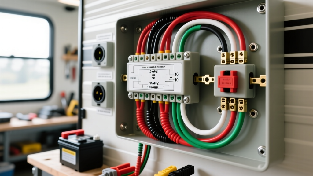
Understanding the 120V 30-Amp Architecture
Before cutting any wire or stripping insulation, it is critical to understand the fundamental architecture of a 30-amp recreational vehicle electrical system. Unlike a 50-amp RV system, which utilizes a 120/240V split-phase configuration requiring a double-pole breaker, a 30-amp travel trailer operates strictly on a 120V single-phase alternating current (AC) circuit. This means your travel trailer 30 amp RV wiring diagram will route a single hot leg, a neutral, and a ground from the shore power inlet directly to a single-pole 30A main breaker.
Misunderstanding this distinction is the most common cause of catastrophic electrical failures in DIY RV builds. Attempting to wire a 30-amp TT-30 system as if it were a 50-amp NEMA 14-50 system will result in immediate short circuits, melted insulation, and severe fire hazards. This practical installation guide will walk you through the exact specifications, wire routing, and termination procedures required to safely install or upgrade your travel trailer's shore power system in compliance with modern safety standards.
Decoding the Travel Trailer 30 Amp RV Wiring Diagram
A standard travel trailer wiring diagram for a 30-amp system follows a linear, highly regulated path governed by NFPA 70 (National Electrical Code) Article 551, which specifically outlines electrical requirements for recreational vehicles and RV parks. The diagram flows as follows:
- Shore Power Cord (TT-30P): Connects to the campsite pedestal (TT-30R).
- Junction Box / Inlet Flange: The point where the external cord enters the RV chassis and transitions to internal wiring.
- Main Disconnect / Distribution Panel: The 10 AWG wires terminate at a single-pole 30A main breaker.
- Branch Circuits & Converter: Power is distributed to 15A/20A branch breakers (AC outlets, microwave, air conditioner) and the AC-to-DC converter/charger.
NEMA TT-30 Pinout and Color Code Specifications
The NEMA TT-30 configuration is unique to the RV industry. It is a 30-amp, 125-volt, 3-wire grounding receptacle. It is physically distinct from NEMA L5-30 (twist-lock) or NEMA 10-30 (dryer) configurations. When referencing your diagram, ensure your internal wire color codes strictly match the NEMA standard to prevent reversed polarity at the pedestal.
| Terminal Designation | Pin Shape / Position | Function | Standard Wire Color | Screw Terminal Color |
|---|---|---|---|---|
| X | Angled Blade (Hot) | 120V AC Line (Hot) | Black | Brass |
| W | Vertical Blade (Neutral) | Neutral Return | White | Silver |
| G | U-Shaped Pin (Ground) | Equipment Grounding | Green or Bare Copper | Green |
Essential Tools and Material Specifications
To execute this installation safely and ensure long-term reliability against the heavy vibrations inherent to travel trailers, you must use the correct materials. Standard residential solid-core Romex (NM-B) is strictly prohibited by the Recreational Vehicle Industry Association (RVIA) and the NEC for use in RVs due to its inability to withstand constant road vibration, which causes solid copper to work-harden, snap, and create high-resistance arcing faults.
- Wire: 10 AWG stranded copper (THHN/THWN-2 or Type SJOOW/SJTOW cordage). Stranded wire is mandatory for vibration resistance.
- Terminals: Insulated ring terminals or closed-end ferrules sized for 10 AWG. Never loop bare stranded wire directly under a screw terminal.
- Crimper: Ratcheting wire crimper (e.g., Titan or IWISS) to ensure gas-tight crimps.
- Torque Tool: Inch-pound torque screwdriver calibrated for electrical terminals.
- Testing: True-RMS Digital Multimeter (DMM) and a dedicated RV 30-amp receptacle tester.
Step-by-Step Shore Power Inlet Installation
Step 1: Prepping the 10 AWG Stranded Conductors
Begin by routing your 10 AWG stranded conductors from the shore power inlet junction box to the main AC distribution panel. Maintain a minimum bend radius of at least four times the cable diameter to prevent internal strand breakage. Strip exactly 5/8-inch of insulation from the wire ends using a precision wire stripper. Avoid scoring the outer copper strands; even minor nicks significantly reduce the wire's ampacity and create localized hot spots under a 30-amp load.
Step 2: Crimping and Terminating the Inlet Flange
Slide a 10 AWG insulated ring terminal over the stripped black (hot) wire and crimp using your ratcheting crimper. Repeat for the white (neutral) and green/bare (ground) wires. Connect the black wire to the brass terminal (X), the white wire to the silver terminal (W), and the ground to the green chassis-bonded terminal (G) on the inlet flange. Tug firmly on each wire to verify the crimp integrity.
Step 3: Routing to the Main Distribution Panel
Secure the wiring every 18 inches using UV-resistant, adhesive-backed cable mounts and nylon zip ties. Ensure the wiring is kept at least 2 inches away from any LP gas lines, exhaust manifolds, or sharp metal chassis edges. Where the wire passes through sheet metal or wooden bulkheads, install rubber grommets or plastic conduit bushings to prevent insulation chafing during transit.
Main Panel Termination and Torque Specifications
The most critical point of failure in any RV electrical system is a loose neutral connection at the main bus bar. A loose neutral in a 120V system causes severe arcing, melting the bus bar and potentially igniting the surrounding wooden cabinetry. According to RVIA standards and general electrical best practices, all terminal screws must be tightened to the manufacturer's specified torque using an inch-pound torque screwdriver.
| Connection Point | Terminal Type | Target Torque (in-lbs) | Target Torque (Nm) |
|---|---|---|---|
| Main 30A Breaker Lug | Setscrew / Box Lug | 20 - 25 in-lbs | 2.2 - 2.8 Nm |
| Neutral Bus Bar | Setscrew | 15 - 20 in-lbs | 1.7 - 2.2 Nm |
| Ground Bus Bar | Setscrew | 15 - 20 in-lbs | 1.7 - 2.2 Nm |
| Inlet Flange Terminals | Machine Screw / Washer | 12 - 15 in-lbs | 1.3 - 1.7 Nm |
Note: Always defer to the specific torque values printed on the label inside your RV's AC distribution panel if they differ from the baseline values above.
Post-Install Multimeter Verification and Testing
Before plugging your travel trailer into a campsite pedestal or applying shore power, you must perform a continuity and isolation test. Set your DMM to the continuity (ohms) setting.
- Hot-to-Ground: Place one probe on the brass (X) terminal and the other on the green (G) terminal. The meter should read 'OL' (Open Loop). Any reading near zero indicates a dead short that will instantly trip the pedestal breaker.
- Neutral-to-Ground: Place probes on the silver (W) and green (G) terminals. This should also read 'OL'. In an RV, the neutral and ground are only bonded at the campsite pedestal transformer or the generator neutral bonding relay, never at the sub-panel or inlet.
- Hot-to-Neutral: Check for continuity. You may read a low resistance (typically 10-50 ohms) due to the primary winding of the RV's AC-to-DC converter/charger or the microwave transformer. This is normal.
Live Voltage Testing
Once continuity tests pass, plug the TT-30P cord into a verified 30-amp pedestal. Using your DMM set to AC Voltage, measure at the main breaker lugs (with the breaker ON):
- Hot (Black) to Neutral (White): Should read 110V - 125V AC.
- Hot (Black) to Ground (Green): Should read 110V - 125V AC.
- Neutral (White) to Ground (Green): Should read less than 1.0V AC. A reading higher than 2V indicates a poor neutral connection at the pedestal or a failing neutral bus bar termination inside your panel.
Voltage Drop Considerations for Long Cable Runs
If you are installing an aftermarket shore power inlet on a large 5th wheel or toy hauler where the distance from the inlet to the main panel exceeds 40 feet, voltage drop becomes a significant factor. 10 AWG copper wire has a resistance of approximately 1.24 ohms per 1,000 feet. A 50-foot one-way run (100 feet total circuit length) carrying a full 30-amp load will experience a voltage drop of roughly 3.72 volts (about 3.1%). While this falls within the NEC's recommended 5% maximum total voltage drop, running high-draw appliances like a 15,000 BTU roof air conditioner simultaneously with a microwave may cause low-voltage tripping on the A/C compressor's hard-start capacitor. If your diagram dictates a run longer than 50 feet, upgrade the main feeder wires to 8 AWG stranded copper to mitigate voltage drop and prevent thermal buildup.
Troubleshooting Common 30-Amp Wiring Faults
Even with a perfect installation, environmental factors and road vibrations can introduce faults over time. Use this diagnostic tree to troubleshoot issues related to your travel trailer 30 amp RV wiring diagram:
- Symptom: Main 30A breaker trips immediately upon plugging into shore power.
Cause: Reversed polarity at the inlet flange, or a shorted heating element in the water heater or refrigerator AC circuit.
Fix: Verify X, W, and G pin mappings. Isolate branch circuits one by one to find the shorted appliance. - Symptom: AC outlets read 90V-105V under load, lights flicker.
Cause: High resistance connection at the neutral bus bar or a corroded TT-30P plug blade.
Fix: Clean plug blades with fine-grit sandpaper. Retorque neutral bus bar screws to 20 in-lbs. - Symptom: Shore power works, but the 12V DC battery bank is not charging.
Cause: The 30A main breaker is supplying the AC panel, but the specific 15A/20A branch breaker feeding the AC-to-DC converter has tripped, or the converter's internal reverse-polarity DC fuses are blown.
Fix: Reset the converter branch breaker. Check the inline DC fuses located on the converter's 12V output terminals.
By strictly adhering to the pinout configurations, utilizing stranded copper, and verifying torque specifications, your 30-amp travel trailer electrical system will provide safe, reliable power for years of camping. For further technical specifications regarding RV wiring methods, always consult the NEMA WD6 dimensional standards and your specific RV manufacturer's schematics.