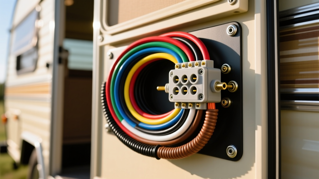
Why Upgrade Your Factory Molded 7-Way RV Plug?
If you tow a travel trailer or fifth wheel, the 7-way blade connector is the critical umbilical cord linking your tow vehicle to your RV's exterior lighting and braking systems. However, most OEM and aftermarket replacement plugs are "molded" or "potted" in hard epoxy. While this seems weatherproof initially, it creates a massive failure point. When the flexible PVC jacket eventually cracks from UV exposure or extreme cold, moisture enters the plug. The epoxy traps this moisture, leading to severe galvanic corrosion. Worse, capillary action can wick this corrosion up the wire strands, ruining feet of your trailer's main harness.
Furthermore, standard molded plugs utilize undersized 14 AWG or even 16 AWG wire for all circuits. When you upgrade to an RV with LED clearance lights, heavy-duty electric drum brakes, or a 12V auxiliary charge line for solar setups, these thin wires suffer from dangerous voltage drop and overheating. By cutting off the molded plug and installing a heavy-duty junction box, you can reference a standard trailer RV plug wiring diagram to rebuild the connection with proper gauge wire, ring terminals, and environmental seals. This modification ensures long-term reliability and optimal electrical flow.
The Standard Trailer RV Plug Wiring Diagram
Before beginning the modification, you must understand the SAE J286 and RVIA standard pinout for 7-way RV blade connectors. Unlike flat 4-way connectors, the 7-way blade includes dedicated circuits for electric brakes and 12V auxiliary power. The physical layout of the plug (viewed from the wiring side, not the pin side) follows a specific clockwise pattern.
| Terminal | Clock Position | Wire Color | Function | OEM AWG | Upgraded AWG |
|---|---|---|---|---|---|
| 1 (Center) | Center | White | System Ground (Chassis) | 14 AWG | 8 AWG |
| 2 | 12 O'Clock | Black | 12V Auxiliary / Battery Charge | 14 AWG | 10 AWG |
| 3 | 2 O'Clock | Yellow | Reverse Lights / Center Aux | 16 AWG | 12 AWG |
| 4 | 4 O'Clock | Green | Tail / Clearance / Running Lights | 16 AWG | 12 AWG |
| 5 | 6 O'Clock | Blue | Electric Trailer Brakes | 14 AWG | 10 AWG |
| 6 | 8 O'Clock | Red | Left Turn / Stop Lights | 16 AWG | 12 AWG |
| 7 | 10 O'Clock | Brown | Right Turn / Stop Lights | 16 AWG | 12 AWG |
Note: Always verify your specific trailer's wiring with a multimeter before final termination, as older or custom-modified trailers may deviate from the Curt Manufacturing standard wiring guides.
Upgrade Bill of Materials & Tools
To execute this modification correctly, you need commercial-grade materials. Do not use cheap vinyl tape or non-insulated crimps.
- Junction Box: 7-Way Trailer Wiring Junction Box (e.g., Curt 57351 or Pollak 31-850) with rubber grommets.
- Terminals: Heat-shrink ring terminals (10-8 AWG for #10 stud, and 12-10 AWG for #10 stud).
- Wire: Stranded, multi-strand copper automotive wire (GXL or TXL cross-linked insulation for high heat resistance).
- Sealing: Adhesive-lined dual-wall heat shrink tubing (3:1 shrink ratio) and dielectric silicone grease.
- Tools: Heavy-duty ratcheting wire crimper, wire strippers, heat gun, torque screwdriver, and digital multimeter.
Step-by-Step Modification: Junction Box Installation
Step 1: Severing and Prepping the Harness
Cut off the old molded plug approximately 12 inches from the base. Strip back the main PVC jacket about 6 inches to expose the individual circuits. Carefully strip 3/8 inch of insulation from each wire. If you are upgrading the wire gauges as recommended in our trailer RV plug wiring diagram table, you will need to splice in pigtails of 10 AWG and 12 AWG GXL wire using adhesive-lined butt connectors. Apply heat until the internal sealant melts and oozes out the ends, ensuring a completely waterproof splice.
Step 2: Crimping Ring Terminals
Slide a piece of 3:1 adhesive heat shrink over each wire before crimping. Insert the stripped wire into the ring terminal barrel. Using a ratcheting crimper set to the appropriate AWG dial, compress the terminal until the ratchet releases. Slide the heat shrink over the barrel and neck of the terminal, then apply heat. This prevents moisture from wicking into the copper strands.
Step 3: Junction Box Termination
Route the wires through the rubber grommet and into the junction box. Following the wiring diagram, place the ring terminals over the corresponding stainless steel posts. The ground wire (White) must be secured to the chassis ground post. Tighten the set screws using a torque screwdriver set to 20 in-lbs. Over-torquing can strip the soft brass or stainless threads, while under-torquing will cause arcing and voltage drop under the heavy load of electric brakes.
Step 4: Environmental Sealing
Once all connections are verified with a multimeter for continuity, pack the interior of the junction box cavity with dielectric silicone grease. This displaces oxygen and moisture, completely eliminating the risk of galvanic corrosion. Secure the lid and wrap the main cable exit grommet with self-fusing silicone rescue tape for an extra layer of UV and water protection.
Pro-Mod: Upgrading the 12V Auxiliary Circuit for Solar
Many modern RVers use the 12V auxiliary pin (Black wire, Pin 2) to charge their RV house battery bank from the tow vehicle's alternator while driving. If your tow vehicle outputs 14.2V, but the RV battery sits at 12.0V, the system will attempt to pull maximum amperage. Standard 14 AWG wire has a resistance of roughly 2.52 ohms per 1,000 feet. Over a 30-foot run from the alternator to the trailer battery, a 20-amp draw will result in a 1.5-volt drop. This means your RV battery only receives 12.7V, drastically reducing charging efficiency and generating excess heat in the plug.
By upgrading the Black 12V auxiliary wire and the White ground wire to 8 AWG or 10 AWG, you drop the resistance significantly. A 10 AWG wire over the same 30-foot distance at 20 amps yields only a 0.6-volt drop, delivering over 13.5V to the RV's charge controller. According to etrailer's comprehensive wiring FAQ, ensuring the ground wire is equal to or thicker than the hot wire is critical for completing this high-amperage circuit safely.
Common Failure Modes & Troubleshooting
Even after upgrading, environmental factors and physical stress can cause issues. Use this decision tree to diagnose post-modification faults:
- Symptom: Electric brakes pulse erratically or lock up at low speeds.
- Cause: Voltage drop on the Blue (Brake) circuit or a loose ground on the White circuit.
- Fix: Check the junction box set screw torque on Pins 1 and 5. Measure voltage at the plug while the brake controller is manually activated; it should read within 0.5V of the controller's output.
- Symptom: Running lights blow fuses in the tow vehicle immediately upon connection.
- Cause: A short to ground on the Green (Tail) wire, often caused by a pinched wire near the trailer tongue or a corroded clearance light fixture.
- Fix: Disconnect the junction box lid. Use a multimeter in continuity mode to test between the Green terminal and the White ground terminal. If continuity exists, trace the harness down the A-frame to find the pinch point.
- Symptom: 12V Auxiliary charge line is not charging the RV house batteries.
- Cause: Blown inline maxi-fuse near the tow vehicle battery, or the Black wire is undersized, triggering the tow vehicle's thermal breaker.
- Fix: Verify the tow vehicle's 12V hot pin with a test light. If hot, check the RV-side 12V circuit breaker. Ensure the upgraded Black wire is securely seated in Pin 2.
By abandoning the flawed molded plug design and executing this junction box modification, you align your trailer's electrical system with true commercial standards. For further reading on RV electrical safety standards, consult the Recreation Vehicle Industry Association (RVIA) standards documentation. A proper junction box upgrade not only prevents roadside electrical failures but also protects your RV's expensive LED lighting arrays and brake controllers from damaging voltage spikes and shorts.