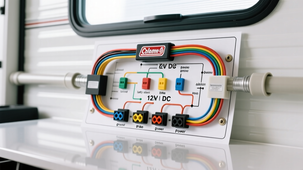
Introduction to Coleman Pop Up Camper Electrical Systems
Owning a Coleman pop up camper—whether it is a classic Fleetwood-era Niagara, a Bayside, or a newer Dutchmen-manufactured model—offers an incredible blend of lightweight towing and comfortable camping. However, the electrical systems in these tent trailers can seem like a labyrinth of colored wires, fuses, and converters to a beginner. Understanding your Coleman pop up camper wiring diagram is the first step toward safe towing, reliable campsite setups, and effective troubleshooting.
Unlike large fifth wheels or motorhomes, pop up campers utilize a simplified, dual-voltage architecture. They rely on a 12-volt DC system for towing safety (lights and brakes) and basic boondocking needs, alongside a 120-volt AC system for shore power appliances. This guide breaks down the fundamental wiring pathways, connector pinouts, and common failure points you need to know to keep your camper's electrical system running flawlessly.
The Dual-Voltage Architecture: 12V DC vs. 120V AC
Before diving into the physical wires, it is critical to understand the two distinct electrical environments in your Coleman pop up. The Recreation Vehicle Industry Association (RVIA) sets strict standards for how these systems must be isolated and grounded to prevent shock hazards and fires.
- 12V DC System: Powered by the tow vehicle via the 7-way plug and a deep-cycle marine/RV battery. It runs the interior LED/incandescent lights, water pump, LP gas detector, and electric brake magnets.
- 120V AC System: Powered by a 15-amp or 30-amp shore power cord when plugged in at a campsite. It runs the roof AC unit (if equipped), microwave, and standard wall outlets.
- The Power Converter: The bridge between the two systems. When plugged into shore power, the converter (typically a WFCO or Iota unit) steps 120V AC down to 13.6V DC to power your 12V accessories and charge your battery.
Decoding the 7-Way RV Plug (Tow Vehicle Connection)
The most common point of failure in any pop up camper wiring diagram is the 7-way blade connector on the tongue. This single plug carries all the DC signals from your tow vehicle to the trailer. Below is the standard RVIA 7-way pinout configuration, complete with standard wire colors and recommended American Wire Gauge (AWG) sizes to prevent voltage drop over the 20-foot run from the hitch to the axle.
| Pin Number | Function | Standard Wire Color | Recommended AWG |
|---|---|---|---|
| 1 (Top Left) | Left Turn Signal / Stop | Yellow | 10 AWG |
| 2 (Top Right) | Reverse Lights / Aux | Black or Red | 12 AWG |
| 3 (Bottom Left) | Chassis Ground | White | 8 AWG |
| 4 (Bottom Right) | Right Turn Signal / Stop | Green | 10 AWG |
| 5 (Center) | Electric Trailer Brakes | Blue | 10 AWG |
| 6 (Top Center) | 12V Battery Charge / Aux | Red or Black | 8 AWG |
| 7 (Bottom Center) | Tail / Running Lights | Brown | 12 AWG |
Expert Tip: Many factory-installed 7-way plugs use 12 AWG wire for the ground and battery charge pins to save money. Upgrading the White (Ground) and Red (12V Charge) wires to 8 AWG will drastically reduce voltage drop, ensuring your breakaway battery stays charged and your lights do not dim when the brakes are applied.
Interior 12V DC Distribution and the Converter
Inside your Coleman pop up, usually located under a dinette bench or near the front closet, you will find the DC fuse panel and the power converter. According to WFCO Technology, modern RV converters operate in three charging stages: Bulk, Absorption, and Float. If your battery is constantly boiling off water or failing to hold a charge, the converter's smart-charging circuitry may have failed, requiring a multimeter test at the DC bus bars.
Standard 12V Interior Wire Color Codes
When reading the internal wiring diagram for your Coleman's DC fuse panel, you will encounter the following color codes:
- White: Universal 12V DC Negative (Ground). This must be bonded to the steel chassis within 18 inches of the battery.
- Red or Black (with inline fuse): 12V DC Positive from the battery to the main bus bar.
- Yellow/Green/Brown: Branch circuits feeding specific lights or the water pump. These are protected by 10A or 15A automotive blade fuses (ATO/ATC style).
The Breakaway Switch and Brake Magnet Circuit
A critical safety component often misunderstood by beginners is the breakaway switch. This small plastic module on the tongue contains a 12V battery and a pull-pin. If the trailer detaches from the hitch, the pin pulls, and the battery sends 12V directly to the blue brake wire, locking the trailer brakes.
Wiring Path: Breakaway Battery Positive → Breakaway Switch → Splices into the Blue (Brake) Wire → Axle Brake Magnets. The magnets ground directly to the axle spindle via a white wire. Never wire the breakaway switch through the main DC fuse panel; it must have a direct, unfused link to the brake circuit to ensure it fires even if the main camper wiring harness is severed in a detachment.
Beginner Troubleshooting Decision Tree
Use this symptom-based guide to diagnose the most common electrical faults in Coleman pop up campers.
Symptom: Interior lights flicker or dim when the tow vehicle brakes are applied.
- Probable Cause: A high-resistance ground connection at the 7-way plug or the main chassis ground bolt on the trailer tongue.
- The Fix: Disconnect the 7-way plug. Inspect the white wire terminal for green copper oxide corrosion. Sand the chassis grounding point down to bare metal, reinstall the ring terminal, and coat it with dielectric grease to prevent future moisture intrusion.
Symptom: The 12V water pump runs, but the interior lights do not turn on.
- Probable Cause: A blown branch circuit fuse on the DC distribution panel, or a faulty 12V wall switch.
- The Fix: Use a multimeter to test the 15A blade fuse labeled 'LTS' or 'CEILING'. If the fuse has continuity, test the 12V rocker switch for output voltage. Pop up campers are prone to vibration; switches often loosen from their spade connectors.
Symptom: Battery drains to 0% after a week in storage.
- Probable Cause: Parasitic draw from the LP gas leak detector, the radio memory, or a faulty converter diode allowing reverse current flow.
- The Fix: Install a heavy-duty marine battery disconnect switch on the positive 8 AWG cable right at the battery terminal. This physically breaks the circuit, eliminating parasitic draws without requiring you to pull cables in tight battery boxes.
Essential Upgrades for Pop Up Camper Wiring
If you are already modifying your Coleman pop up camper wiring diagram, consider these two high-impact upgrades:
- Full LED Conversion: Factory incandescent 1141 bulbs draw roughly 1.8 amps each. Replacing them with 921 LED bulbs drops the draw to 0.2 amps. This reduces the load on your 12V wiring, eliminates heat buildup in canvas-adjacent fixtures, and extends boondocking battery life by up to 400%.
- 7-Way Junction Box: Instead of splicing wires under the trailer with butt connectors (which fail due to road spray and vibration), install a sealed 7-way junction box on the tongue. Run a single, heavy-duty 7-conductor cable to the box, and use ring terminals to connect to the trailer's wiring harness. This makes future diagnostics and wire replacements significantly easier.
Conclusion
Mastering your Coleman pop up camper wiring diagram does not require an electrical engineering degree. By understanding the separation of 12V and 120V systems, respecting the RVIA color codes, and maintaining clean, heavy-gauge ground connections, you can ensure your tent trailer remains safe and reliable for years to come. Always consult your specific model year's owner manual and use a digital multimeter before cutting or splicing any factory harness. For further reading on RV electrical codes and safety standards, refer to the Curt Manufacturing towing guides and the RVIA safety bulletins.