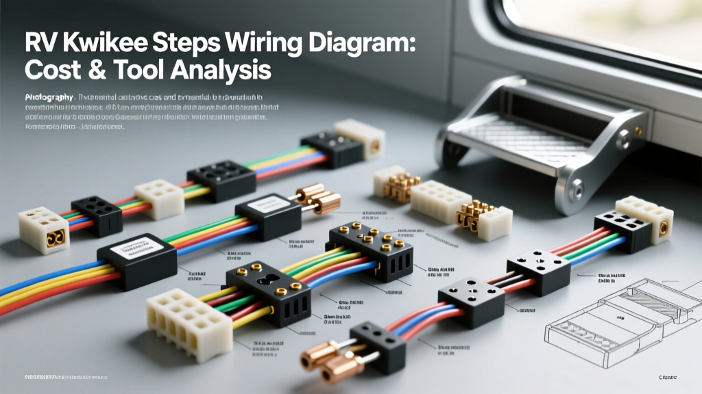
Decoding the Kwikee Steps Wiring Diagram and System Logic
When a motorized RV entry step fails, the immediate instinct is often to replace the entire assembly. However, a deep dive into the kwikee steps wiring diagram reveals that a vast majority of failures stem from degraded wiring, corroded grounds, or failed control modules rather than the mechanical step unit itself. Kwikee (now a Lippert brand) step systems, particularly the ubiquitous Series 32, 36, and 42 models, rely on a precise 12V DC logic circuit to manage deployment and retraction safely.
The standard Kwikee 4-pin control harness utilizes specific color-coded wires to manage power, grounding, and safety overrides. Understanding this schematic is the first step in performing an accurate cost and tool requirements analysis before beginning any repair or custom installation.
- Red Wire (12V+ Constant Power): Routed directly from the coach battery bank through a 20A or 30A auto-reset circuit breaker. This provides the high-amperage current required for the motor's stall and running phases.
- Black Wire (Chassis Ground): Must be terminated to a clean, bare-metal chassis ground. A poor ground is the number one cause of sluggish step operation and control module burnout.
- White Wire (Door Switch Signal): Connects to the magnetic door switch. When the door closes, the switch grounds this wire, signaling the module to retract the steps.
- Yellow Wire (Ignition Override): Tied to the vehicle's ignition 'run' circuit. If the engine is started while the door is open, this 12V+ signal overrides the door switch and forces the steps to retract, preventing catastrophic damage while driving.
Essential Tool Requirements for Installation and Repair
Working on high-current 12V DC RV systems requires specialized automotive and marine-grade tools. Standard household electrical tools will result in poor crimps, voltage drop, and potential fire hazards. Below is the mandatory tool checklist for executing a reliable Kwikee step wiring repair.
Crimping and Wire Preparation
Do not use non-ratcheting crimpers for 10 AWG power wires. You must use a ratcheting wire crimper calibrated for 10-14 AWG terminals to ensure a gas-tight connection. For the control module pigtail, a micro-crimper for 18-22 AWG Deutsch or Molex pins is required if you need to replace a damaged connector housing.
Testing and Diagnostics
A digital multimeter (DMM) capable of measuring DC voltage and continuity is non-negotiable. You will need to test for voltage drop across the ground circuit and verify the 12V+ signal on the yellow ignition override wire. Additionally, a magnetic switch alignment tool (or a simple compass) helps verify the polarity and actuation distance of the door sensor.
Weatherproofing Materials
RV steps are exposed to extreme road spray, salt, and mud. All connections must be sealed using marine-grade adhesive-lined heat shrink (3M or Ancor brand). Standard electrical tape will unravel and absorb moisture within a single season, leading to rapid copper oxidation.
Comprehensive Cost Analysis: OEM vs. Targeted Repair
Budgeting for a Kwikee step repair requires distinguishing between a full mechanical replacement and an electrical overhaul. The table below breaks down the estimated costs for a standard Series 32 Kwikee step system repair versus a complete OEM replacement.
| Component / Service | Targeted Wiring Repair Cost | Full OEM Assembly Replacement Cost |
|---|---|---|
| Control Module (4-Pin) | $110.00 - $145.00 | Included in Assembly |
| 12V DC Motor Assembly | $180.00 - $240.00 | Included in Assembly |
| Magnetic Door Switch & Harness | $15.00 - $25.00 | $15.00 - $25.00 (Sold Separately) |
| 10 AWG & 14 AWG Marine Wire (20ft) | $35.00 - $50.00 | $0.00 (Reuses Coach Wiring) |
| 30A Type-1 Auto-Reset Breaker | $12.00 - $18.00 | $12.00 - $18.00 |
| Connectors, Heat Shrink, Loom | $25.00 - $40.00 | $10.00 |
| Total Estimated Material Cost | $377.00 - $518.00 | $650.00 - $850.00+ |
As demonstrated, if the mechanical linkages and gear teeth are intact, rebuilding the wiring harness and replacing the control module yields a savings of nearly 40%. However, if the motor's internal gearbox is stripped, the cost of the motor assembly alone pushes the repair budget close to the price of a complete drop-in replacement unit.
Wire Gauge (AWG) and Voltage Drop Calculations
The most frequently overlooked aspect of the kwikee steps wiring diagram is the distance from the coach battery bank to the step well. RVs often feature battery compartments located in the front or rear, requiring wire runs of 15 to 30 feet. The Kwikee 12V motor draws approximately 10 to 15 amps under normal load, but can spike to 25 amps during stall or if the mechanical linkages are binding due to lack of lubrication.
According to SAE J1128 standards for low-tension primary cable, undersized wiring will cause severe voltage drop. If the voltage at the motor drops below 10.5V under load, the motor will overheat, and the control module's internal relays may weld shut due to excessive arcing.
| Total Wire Run (Positive + Negative) | Minimum AWG Required (15A Load) | Recommended AWG (20A+ / High Safety Margin) |
|---|---|---|
| Under 10 Feet | 14 AWG | 12 AWG |
| 10 to 20 Feet | 12 AWG | 10 AWG |
| 20 to 35 Feet | 10 AWG | 8 AWG |
| Over 35 Feet | 8 AWG | 6 AWG |
Always use stranded, multi-strand marine-grade copper wire (Type 3 stranding) rather than solid core or cheap automotive CCA (Copper Clad Aluminum) wire. CCA wire has higher resistance and is highly prone to snapping under the constant vibration of the RV chassis.
Execution Best Practices and Safety Overrides
When routing the new harness, adhere strictly to NFPA 1192 Standard on Recreational Vehicles guidelines for 12V DC wiring. All wires passing through the RV's steel or aluminum floor pan must be protected by rubber grommets and split loom tubing to prevent chafing and short circuits.
Furthermore, never bypass the yellow ignition override wire. Bypassing this safety feature to save time during a custom camper build or repair will result in the steps deploying or remaining extended while the vehicle is in motion. Always verify the ignition override circuit with a multimeter to ensure it only receives 12V+ when the key is in the 'ON' or 'RUN' position, and drops to 0V in the 'ACC' or 'OFF' positions.
For comprehensive installation schematics and torque specifications for the motor mounting bolts (typically 1/4'-20 UNC, torqued to 7-9 ft-lbs), refer to the official Lippert Components Technical Manuals portal. Proper electrical integration combined with mechanical maintenance ensures your Kwikee steps will operate reliably for the lifespan of the RV.