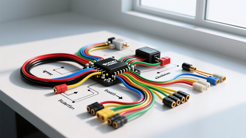
Introduction to the Suzuki GSX-R 600 Electrical System
The Suzuki GSX-R 600 is a legendary track-focused sportbike, but beneath its aggressive fairings lies an electrical system that can intimidate new owners. Whether you are trying to diagnose a dead battery, install a USB charger, or upgrade to LED turn signals, understanding the Suzuki GSXR 600 wiring diagram is your first step toward motorcycle electrical independence. Unlike older, simpler bikes, the modern GSX-R relies on an Engine Control Module (ECM), a complex stator output, and multiple safety interlock switches. However, Suzuki’s engineering logic is remarkably consistent. Once you learn how to read their factory schematics and decode their standardized color palette, troubleshooting becomes a systematic process rather than a guessing game.
How to Read a Suzuki Factory Wiring Diagram
Factory service manuals organize wiring diagrams by system rather than physical routing. You will typically find separate schematics for the charging system, ignition system, lighting, and ECM sensors. When looking at a Suzuki diagram, power sources (battery positive) are usually at the top or left, while ground points are at the bottom or right. Splices are indicated by a solid black dot where wires intersect, while crossing wires without a dot mean they do not connect.
Decoding Suzuki Wire Color Codes
Suzuki uses a highly standardized, alphanumeric color-coding system across almost all its motorcycles. Wires are either a solid color or a base color with a tracer (stripe). In the wiring diagram, a Black wire with a White stripe is written as B/W. Memorizing these core colors will save you hours of tracing harnesses with a multimeter.
| Code | Color | Primary Function |
|---|---|---|
| R | Red | Unswitched Battery Positive (Main Power) |
| B | Black | Main Ground / Earth |
| B/W | Black/White | Sensor Ground / ECM Ground |
| O | Orange | Ignition Switched Positive (Key ON power) |
| Y | Yellow | Stator AC Output (Alternator Phase Wires) |
| W | White | Lighting / High Beam / Accessory Power |
| Br | Brown | Tail Light / Running Light Positive |
| Lg | Light Green | Right Turn Signal Positive |
| L | Blue | Left Turn Signal / High Beam Indicator |
Core Circuits Every GSX-R 600 Owner Must Know
The Stator and Rectifier/Regulator Circuit
The charging system is the most common failure point on high-revving inline-four sportbikes. The stator, located behind the left engine cover, generates 3-phase Alternating Current (AC). If you look at the GSXR 600 wiring diagram for the charging system, you will see three thick Yellow (Y) wires exiting the stator and routing to the Rectifier/Regulator (R/R).
Real-World Failure Mode: The OEM 3-pin Sumitomo connector linking the stator to the R/R is notorious for melting. The stator can output over 30 Amps at high RPMs. Over time, vibration and moisture increase the resistance at the connector pins. According to SAE J1128 standards for low-tension primary cable, increased resistance leads to excessive heat (I²R losses), eventually melting the plastic housing and causing a dead battery or a fried ECM. The Fix: Many experienced mechanics cut out the OEM connector and solder the three Yellow wires directly to the R/R, sealing them with marine-grade adhesive heat shrink, or upgrade to heavy-duty 30A-rated waterproof bullet connectors.
Ignition and Safety Interlock Logic
Modern GSX-R models feature a safety interlock system that prevents the bike from starting in gear with the kickstand down. The wiring diagram shows this logic flowing through the clutch switch, neutral switch, and sidestand switch. When troubleshooting a 'no-crank' condition, beginners often blame the starter motor or solenoid. However, using a multimeter to check for 12V on the Orange/White (O/W) wire at the starter relay coil when the start button is pressed will instantly tell you if the ECM is permitting the start sequence. If there is no voltage, trace the interlock switches before replacing expensive starter components.
Beginner DIY Mods: Adding Accessories Safely
One of the most common reasons beginners search for a Suzuki GSXR 600 wiring diagram is to install aftermarket accessories. The golden rule of sportbike electrics is: Never tap directly into the ECM harness or the main ignition feed. The ECM operates on low-voltage, highly sensitive 5V reference signals. Introducing voltage drop or resistance can cause erratic fueling or throw a FI (Fuel Injection) code.
Upgrading to an LED Flasher Relay
Swapping OEM 21W incandescent turn signal bulbs for low-draw LEDs will cause the signals to 'hyperflash' because the OEM thermal flasher relay relies on the heat generated by the higher amperage draw to break the circuit.
- Step 1: Locate the OEM flasher relay under the tail section or behind the left side fairing (consult your specific year's diagram, as K6-K11 routing varies slightly).
- Step 2: The OEM Suzuki relay typically uses a 2-pin or 3-pin connector. Identify the Light Green/Black (Lg/Bk) wire (power from turn signal switch) and the Black/White (B/W) ground wire.
- Step 3: Install a direct plug-and-play 2-pin electronic LED flasher relay designed for Suzuki. Electronic relays use a microchip to time the flash rate regardless of the electrical load, completely solving the hyperflash issue without needing ugly load resistors.
Tapping into the Tail Light for a USB Charger
If you want to add a switched USB charger for your phone or GPS, the tail light circuit is a safe, low-draw source.
- Locate the tail light connector. You are looking for the Brown (Br) wire (running light positive) and the Black/White (B/W) wire (ground).
- Do NOT use the brake light wire (usually Red/Black or similar), as your accessory will turn off when you release the brake lever.
- Use a Posi-Tap connector to tap the Brown wire. This pierces the wire cleanly without cutting the copper strands, preserving the structural integrity of the 18 AWG harness wire.
- Route the new leads to an inline 5A ATC fuse holder, then to your USB step-down module. Always place the fuse as close to the power tap point as possible to protect the harness in the event of a short circuit.
Essential Tools and Troubleshooting Tips
To effectively use the GSXR 600 wiring diagram, you need the right tools. A basic test light is insufficient for modern fuel-injected motorcycles and can actually damage the ECM by drawing too much current. Invest in a high-quality digital multimeter (DMM) with a high-impedance input.
When testing sensors like the Throttle Position Sensor (TPS) or the Intake Air Temperature (IAT) sensor, you are measuring 5V reference signals and variable resistance. Use the back-probing method: insert a fine T-pin into the back of the sealed Sumitomo connector while it is plugged into the ECM. This allows you to read live data without piercing the wire insulation, which can invite corrosion into the copper strands. According to resources like Electrosport Industries, maintaining clean, moisture-free connections is critical for the longevity of motorcycle stators and sensors.
Understanding Wire Gauge (AWG) and Voltage Drop
When repairing or extending wires, always match the American Wire Gauge (AWG) to the OEM specification.
- 8-10 AWG: Main battery leads, starter motor cables, and main ground straps. These carry 30A to 100A+ during cranking.
- 12-14 AWG: Stator outputs (Yellow wires), main headlight power feeds, and cooling fan circuits.
- 16-18 AWG: Tail lights, turn signals, horn, and general accessory circuits.
- 20-22 AWG: ECM sensor signals, injector pulses, and low-current data lines.
Authoritative Resources for Further Study
While this guide provides the fundamentals, always cross-reference your specific model year's factory service manual. The Suzuki Service Manuals contain the exact pinout charts for the ECM connectors, which are vital for deep diagnostics. Additionally, understanding the SAE J1128 standard for low-tension primary cable will help you select the correct automotive-grade wire (like TXL or GXL cross-linked polyethylene insulation) for any custom harness work you undertake on your GSX-R 600.