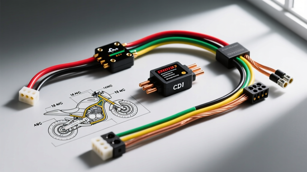
Understanding Pit Bike Electrical Architecture
When modifying, repairing, or building a pit bike from scratch, selecting the correct electrical harness is the most critical step. The universal pit bike wiring diagram you choose to follow will dictate your stator type, CDI unit, rectifier, and lighting capabilities. Most 110cc, 125cc, 140cc, and 190cc pit bikes (including SSR, Apollo, Thumpstar, and Honda CRF clones) utilize simplified electrical systems derived from older Honda architecture. However, the aftermarket offers vastly different harness products depending on whether you need a basic race setup or a fully street-legal DC lighting system.
Product Comparison: Harness Kit Categories
Before tracing a single wire, you must select the harness product that matches your build goals. Below is a technical comparison of the three primary pit bike wiring harness kits available on the market.
| Feature | OEM-Style AC Replacement Harness | Minimalist Race Harness (Kill Switch Only) | DC-Conversion Lighting Harness |
|---|---|---|---|
| Stator Requirement | Half-Wave AC Stator | AC or DC Stator (Lighting coils unused) | Full-Wave DC Stator (Rewound or aftermarket) |
| Battery Required? | No (Optional for accessories) | No | Yes (12V 4Ah to 7Ah AGM/LiFePO4) |
| Headlight Power | AC Direct (Flickers with RPM) | N/A | DC Regulated (Steady at idle) |
| CDI Compatibility | AC-CDI (5-Pin or 6-Pin) | AC-CDI or DC-CDI | DC-CDI (6-Pin required) |
| Best Application | Restoring stock trail bikes | Dedicated motocross / pit racing | Supermoto, dual-sport, night riding |
Decoding the Standard Pit Bike Wiring Diagram
Chinese-manufactured pit bikes largely adhere to the Honda wire color code standard, but inconsistencies between factories are common. Always verify with a multimeter before splicing. According to baseline Haynes motorcycle repair manuals for Honda CRF50/110 models, which serve as the blueprint for most clone engines, the standard color coding is as follows:
| Wire Color | Function | Voltage / Signal Type |
|---|---|---|
| Red | Battery Positive (Constant 12V) | 12V DC |
| Black | Switched 12V (Ignition Key Output) | 12V DC (Switched) |
| Green | Chassis Ground | 0V (Continuity to Engine Case) |
| Yellow | Stator AC Output (Lighting Coil) | 12V-30V AC (RPM Dependent) |
| White | Stator AC Output (Charging Coil) | 12V-30V AC (To Rectifier) |
| Blue / White | Pulse Generator (Pickup Coil Signal) | AC Voltage Spike (Trigger) |
| Black / White | Engine Kill Switch | Grounds CDI to kill spark |
| Black / Red | CDI to Ignition Coil Trigger | High Voltage Pulse |
| Green / White | Front Brake Light Switch | 12V DC Switched Ground |
| Green / Yellow | Rear Brake Light Switch | 12V DC Switched Ground |
Stator and Rectifier Selection for DC Conversions
If your chosen pit bike wiring diagram includes DC lighting (LED headlamps, turn signals, and a horn), the stock half-wave stator will not suffice. A half-wave stator only utilizes one half of the AC sine wave, resulting in poor low-RPM charging. You must upgrade to a full-wave stator.
A full-wave stator outputs two Yellow wires (instead of one Yellow and one White). Both Yellow wires must route directly to a full-wave voltage regulator/rectifier. The rectifier converts the dual-phase AC into a clean 14.2V DC output to charge the battery and power accessories. Attempting to run a DC lighting harness on a half-wave AC stator will result in severe voltage drops at idle, causing LED lights to strobe and the battery to drain rapidly.
CDI Ignition Matching: AC vs. DC Units
The Capacitor Discharge Ignition (CDI) unit must match your stator and harness. Installing a DC-CDI on an AC harness will result in zero spark, as the DC-CDI expects a 12V battery feed rather than high-voltage AC from the stator's dedicated ignition winding.
6-Pin DC-CDI Pinout Configuration
- Pin 1 (Red): +12V DC from Ignition Switch
- Pin 2 (Green): Chassis Ground
- Pin 3 (Blue/White): Pickup Coil Signal
- Pin 4 (Black/White): Kill Switch (Ground to kill)
- Pin 5 (Black/Yellow): Trigger to Ignition Coil
- Pin 6 (Empty/Tach): Tachometer signal (often unused)
5-Pin AC-CDI Pinout Configuration
- Pin 1 (Green): Chassis Ground
- Pin 2 (Blue/White): Pickup Coil Signal
- Pin 3 (Black/White): Kill Switch
- Pin 4 (Black/Red): High Voltage AC from Stator Ignition Winding
- Pin 5 (Black/Yellow): Trigger to Ignition Coil
Wire Gauge and Connector Specifications
Many budget pit bike harnesses use undersized 20 AWG wire and low-grade JST-SM plastic connectors, which are prone to vibration failure and moisture ingress. When building a custom harness or repairing a damaged one, adhere to SAE J1128 standards for low-tension primary automotive cable.
- Signal Wires (Pickup, Kill Switch, Brake Switches): 18 AWG stranded copper.
- Lighting and Charging Circuits: 16 AWG stranded copper to prevent voltage drop over long runs to the headlight.
- Main Battery Feeds and Starter Solenoid: 14 AWG or 12 AWG (if equipped with a 12V starter motor).
For connectors, discard the stock JST plugs. Crimp and seal your connections using Molex MX150 or Aptiv (Delphi) Weather-Pack connectors. These feature silicone secondary locks and rubber seals that withstand the high-vibration, high-mud environment of pit bike racing.
Troubleshooting Common Harness Failures
Use this decision tree to diagnose electrical faults based on your wiring diagram:
- Symptom: No Spark, but Stator tests good.
- Check: Black/White kill switch wire. If it has continuity to ground while the key is ON, the kill switch is shorted or wired backwards.
- Check: CDI type mismatch. Verify you are not supplying 12V DC to an AC-CDI stator power pin.
- Symptom: Headlight blows out at high RPM.
- Cause: Running an AC headlight on a DC harness without a voltage regulator, or a failed half-wave rectifier.
- Fix: Install an inline AC voltage regulator on the Yellow stator wire before the headlight switch, or convert to a DC LED headlight powered by the battery.
- Symptom: Battery drains overnight.
- Cause: Incorrect rectifier wiring allowing AC ripple back into the DC system, or a brake light switch stuck closed (Green/White or Green/Yellow shorted to ground).
- Fix: Disconnect the battery negative terminal and place a multimeter in series (Amps). Pull fuses one by one to isolate the parasitic draw circuit.
Final Selection Advice
Choosing the correct pit bike wiring diagram and corresponding harness kit ultimately depends on your engine's stator output and your intended riding environment. For pure track bikes, strip the harness down to the ignition essentials using a 5-pin AC-CDI and a minimalist race harness. For supermoto or dual-sport builds, invest the time to rewind or replace your stator for full-wave output, utilize a 6-pin DC-CDI, and build a custom harness using 16 AWG wire and sealed Weather-Pack connectors. Proper planning and adherence to standardized wire colors will save hours of frustrating multimeter troubleshooting down the line.