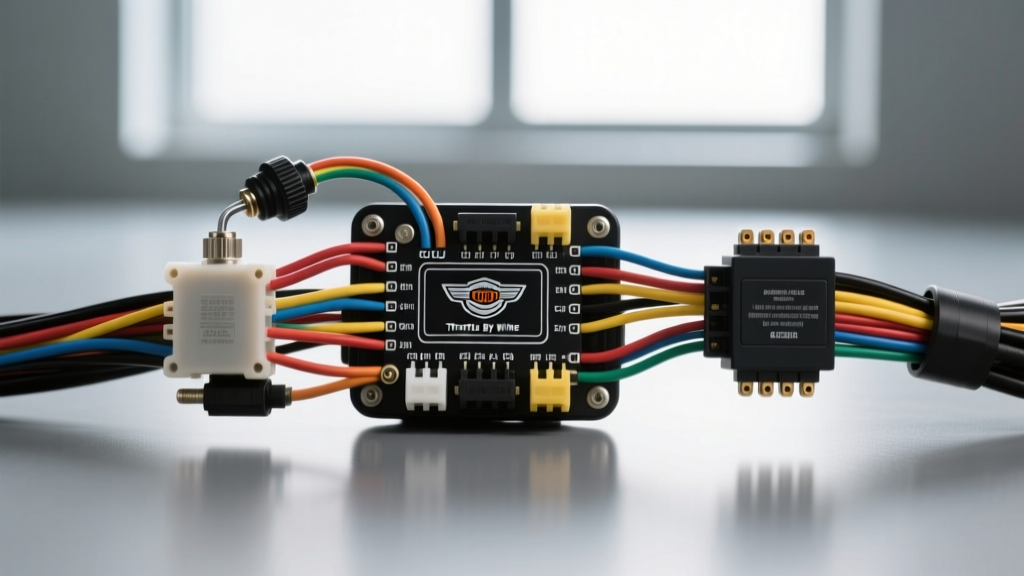
Understanding the Harley-Davidson Electronic Throttle Control (ETC) Architecture
Beginning with the 2008 Touring models and expanding to the 2011 Softail lineup, Harley-Davidson transitioned from mechanical cable actuation to a fully redundant Electronic Throttle Control (ETC) system. When interpreting a throttle by wire Harley wiring diagram, technicians and custom builders must understand that this is not a simple variable resistor circuit. It is a closed-loop, safety-critical network governed by strict SAE electronic throttle control safety standards. The system relies on a Twist Grip Sensor (TGS) at the handlebars and a DC actuator motor at the throttle body, both managed by the Engine Control Module (ECM). Because a failure in this circuit results in immediate Limp Mode or engine shutdown, diagnosing and repairing the harness requires specialized tools, precise wire gauge matching, and a clear understanding of the associated costs.
Decoding the Throttle By Wire Harley Wiring Diagram
The TBW harness is divided into two primary sub-circuits: the low-voltage sensor reference loop and the high-current actuator drive loop. Both utilize sealed Deutsch DT series connectors to prevent moisture ingress and vibration-induced terminal fretting.
Twist Grip Sensor (TGS) Pinout and Wire Colors
The TGS utilizes dual Hall-effect sensors to provide redundant position data. The ECM monitors both signals; if they do not correlate within a pre-programmed algorithmic window, the ECM triggers a P0211 or P0212 Diagnostic Trouble Code (DTC) and limits RPM.
| Pin | Function | Wire Color (Typical) | AWG | Circuit Notes |
|---|---|---|---|---|
| 1 | 5V Reference | Pink | 20 AWG | Shared 5V logic from ECM. Voltage drop causes limp mode. |
| 2 | Sensor Ground | Black | 20 AWG | Must have less than 0.05V drop to ECM ground. |
| 3 | Signal 1 (Primary) | Green/White | 20 AWG | 0.5V (closed) to 4.5V (WOT). |
| 4 | Signal 2 (Redundant) | Violet/White | 20 AWG | Inverse or offset correlation to Signal 1. |
| 5-6 | Reserved | N/A | N/A | Empty cavities, plugged for weather sealing. |
Throttle Body Actuator Motor Circuit
Unlike the sensor side, the actuator motor requires higher current to physically pull the throttle blade open against spring tension. The ECM uses an internal H-bridge to drive the motor in both directions.
- Pin 1 (Motor Drive +): White/Red wire, 16 AWG. Carries pulsed DC voltage from the ECM H-bridge.
- Pin 2 (Motor Drive -): White/Black wire, 16 AWG. Return path for the actuator circuit.
Expert Note: Never apply 12V directly from a battery to the actuator motor pins to 'test' it. The sudden voltage spike can fry the ECM's internal H-bridge transistors, turning a $40 wiring repair into a $600 ECM replacement.
Specialized Tool Requirements for TBW Diagnostics
Standard automotive electrical tools are insufficient for Harley TBW systems. The Deutsch DT connectors use solid cylindrical machined contacts, not stamped open-barrel terminals. Attempting to crimp these with standard pliers will result in a high-resistance connection that fails under engine vibration.
Essential Diagnostic and Repair Tooling
| Tool | Purpose | Estimated Cost |
|---|---|---|
| Deutsch 4-Indent Crimper (e.g., Hozan P-706) | Properly crimps solid DT pins/sockets without damaging the wire core. | $65 - $120 |
| HD-48063 ECM Breakout Box | Allows safe back-probing of the 35-pin Delphi ECM connector without spreading terminals. | $120 - $180 |
| Fluke 87V True RMS Multimeter | Required for accurate PWM voltage readings on the actuator motor circuit. | $400+ |
| DT Insertion/Extraction Tool | Removes wedgelocks and releases terminal retention fingers safely. | $15 - $25 |
| Dielectric Grease (NYE 812A) | Prevents galvanic corrosion inside the TGS connector boot. | $20 |
Cost Analysis: Dealership vs. DIY TBW Repair
The financial barrier to entry for TBW repair is heavily skewed toward diagnostic tooling and OEM component costs. Understanding the cost breakdown helps builders and owners decide whether to invest in personal tooling or pay dealership premiums.
Component and Labor Cost Breakdown
- OEM Twist Grip Sensor Assembly: $180 - $240. (Harley does not officially sell the internal sensor separate from the grip housing, though aftermarket pigtails exist).
- OEM Throttle Body Assembly: $350 - $450. (The actuator motor and internal Throttle Position Sensor are integrated; if the motor fails, the entire throttle body must be replaced).
- Dealership Diagnostic Fee: $150 - $200 (Typically 1 to 1.5 hours at $150/hr just to hook up the Digital Technician II and read the DTCs).
- DIY Harness Repair Kit: $35 - $50. (Includes 3-cavity Deutsch DT plug, solid contacts, wedgelocks, and adhesive-lined heat shrink).
The Break-Even Analysis: If your TBW issue is caused by a chafed 5V reference wire or a corroded TGS connector pin—a very common failure mode on 2008-2015 models—a dealership will often quote a full grip replacement plus diagnostic time, totaling upwards of $400. By investing $90 in a proper Deutsch crimper and $40 in a repair pigtail, you can splice and seal the harness in 45 minutes, saving over $250 on the first repair alone.
Real-World Failure Modes and Troubleshooting Steps
When referencing Haynes and OEM Harley-Davidson service documentation, the most prevalent TBW failure is not a dead sensor, but a compromised ground or 5V reference circuit due to water intrusion at the handlebar connector.
Symptom: Intermittent Limp Mode in Rain or High Humidity
- Visual Inspection: Disconnect the TGS connector. Check for green/white corrosion on the solid pins. Inspect the rear silicone wire seal; if it is deformed or missing, water has wicked into the harness.
- Voltage Drop Test: Turn the ignition ON (engine off). Back-probe the ECM side of the 5V Reference (Pink wire). You should read exactly 4.95V to 5.05V. If you read 4.6V, you have a high-resistance fault between the ECM and the grip.
- Actuator Resistance Check: Disconnect the throttle body actuator connector. Measure resistance across the two motor pins (White/Red and White/Black). A healthy DC motor should read between 2.0 and 4.5 Ohms. An open circuit (OL) indicates a burnt motor brush or broken internal winding.
Best Practices for Harness Repair and Sealing
When splicing a new Deutsch pigtail into the main harness, solder-seal splices are highly recommended over butt connectors for the 20 AWG sensor wires. The 5V logic circuit is highly sensitive to resistance; a poorly crimped butt connector can add 0.5 Ohms of resistance, which is enough to skew the Hall-effect sensor reading by 2-3%, triggering a correlation DTC. Always use dual-wall, adhesive-lined heat shrink (3M MDT or equivalent) to create a waterproof environmental seal, and route the repaired harness away from the exhaust header and steering stem to prevent tension and heat degradation.