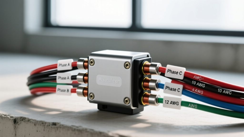
Understanding the 3-Phase Charging Circuit Topology
The modern motorcycle charging system relies on a permanent magnet alternator (stator) and a combined regulator/rectifier (R/R) unit to convert mechanical energy into usable DC electrical power. When referencing a motorcycle regulator rectifier wiring diagram, it is critical to understand that the stator generates wild, unregulated 3-phase alternating current (AC). The rectifier section of the R/R uses a diode bridge to convert this AC into direct current (DC), while the regulator section modulates the output to maintain a strict 14.2V to 14.8V DC window, preventing battery overcharge and electrical component damage.
Historically, most OEMs utilized Silicon Controlled Rectifier (SCR) shunt regulators. These units regulate voltage by short-circuiting the stator coils to ground when the battery reaches full charge, bleeding excess energy as heat. Modern upgrades favor MOSFET series regulators, which physically open the circuit to interrupt current flow, drastically reducing heat soak and stator degradation. According to Electrosport Industries Technical Articles, understanding the distinction between shunt and series topologies is essential when interpreting wiring schematics and planning harness upgrades.
Standard Motorcycle Regulator Rectifier Wiring Diagram Layouts
While OEM harnesses vary in connector shape and wire color, the fundamental electrical pathways remain consistent across Japanese, American, and European platforms. Below are the standard pinout configurations for the most ubiquitous R/R units found in the aftermarket and OEM replacement sectors.
5-Pin Shindengen SCR Shunt Regulator Pinout
The 5-pin configuration is the industry standard for traditional shunt regulators (e.g., Shindengen SH636 series). It utilizes three phases for AC input and two heavy-gauge wires for DC output.
| Pin Number | Function | Standard Wire Color | Signal Type | AWG Requirement |
|---|---|---|---|---|
| 1 | Stator Phase A | Yellow | 3-Phase AC Input | 14 AWG |
| 2 | Stator Phase B | Yellow | 3-Phase AC Input | 14 AWG |
| 3 | Stator Phase C | Yellow | 3-Phase AC Input | 14 AWG |
| 4 | Battery Positive (+) | Red | Regulated DC Output | 10 AWG |
| 5 | Ground / Battery (-) | Green / Black | Chassis Ground | 10 AWG |
6-Pin MOSFET Series Regulator Pinout
Upgrading to a MOSFET series regulator (such as the legendary Shindengen SH775) often requires adapting to a 6-pin connector. This design separates the DC output and ground pathways to handle higher continuous current loads without connector melting. Shindengen America specifies this architecture to minimize voltage drop across the rectifier bridge under heavy accessory loads.
| Pin Number | Function | Standard Wire Color | Signal Type | AWG Requirement |
|---|---|---|---|---|
| 1 | Stator Phase A | Yellow | 3-Phase AC Input | 12 AWG |
| 2 | Stator Phase B | Yellow | 3-Phase AC Input | 12 AWG |
| 3 | Stator Phase C | Yellow | 3-Phase AC Input | 12 AWG |
| 4 | Battery Positive (+) | Red | Regulated DC Output | 10 AWG |
| 5 | Ignition / Sense Wire | Black / White | Switched 12V DC | 16 AWG |
| 6 | Ground / Battery (-) | Green / Black | Chassis Ground | 10 AWG |
Wire Gauge (AWG) and Terminal Specifications
A frequent point of failure in motorcycle charging systems is the use of undersized wiring and improper terminal crimps. The stator-to-R/R circuit carries high-amperage AC current, which is highly susceptible to voltage drop and resistive heating. Per SAE Technical Standards Board guidelines for automotive and marine electrical systems, wire gauge must be selected based on continuous current load and harness length.
- Stator to R/R (AC Input): Minimum 14 AWG stranded copper. For high-output stators (45A+), upgrade to 12 AWG to reduce thermal buildup inside the connector cavity.
- R/R to Battery (DC Output): Minimum 10 AWG stranded copper. The positive and ground paths must handle the full DC load of the motorcycle. Using 12 AWG or smaller on the DC output side will cause a voltage drop, forcing the regulator to overcompensate and cook the battery.
- Terminals: Use non-insulated, brazed-seam ring terminals for battery and chassis grounds. Crimp using a ratcheting tool (e.g., TE Connectivity CERTI-CRIMP II or Hozan P-706) to ensure optimal cold-weld compression. Torque M6 ring terminal hardware to 8-10 Nm.
OEM-Specific Stator Wire Color Codes
While the internal logic of the regulator rectifier remains constant, OEMs utilize varying color codes for the stator output wires. When tracing a factory motorcycle regulator rectifier wiring diagram, use this cross-reference chart to identify the AC input phases before splicing into an aftermarket harness.
| Manufacturer | Phase A | Phase B | Phase C | Common Connector Type |
|---|---|---|---|---|
| Honda / Yamaha | Yellow | Yellow | Yellow | Sumitomo HM 090 (3-cavity) |
| Suzuki | White | White | White | Sumitobe HM 090 (3-cavity) |
| Kawasaki | Black/Yellow | Black/Yellow | Black/Yellow | Tyco/TE Econoseal |
| Harley-Davidson (V-Twin) | Yellow | Yellow | N/A (Single Phase) | Deutsch DT / Packard |
Diagnostic Testing and Benchmark Specifications
Troubleshooting a charging system requires isolating the stator from the regulator. Never rely solely on battery voltage to diagnose a faulty R/R. Follow these benchmark tests using a true-RMS digital multimeter.
Phase-to-Phase AC Output Test
- Disconnect the 3-pin stator connector from the regulator rectifier.
- Set the multimeter to AC Voltage (VAC).
- Start the engine and raise RPM to 3,000.
- Measure across Phase A to B, B to C, and A to C.
- Specification: You should read between 40VAC and 70VAC across all three pairs. If one pair reads significantly lower (e.g., 15VAC), the stator has a shorted winding or a broken internal lead, not a faulty regulator.
Regulated DC Output and Ripple Voltage
- Reconnect the stator to the R/R and connect the battery.
- Set the multimeter to DC Voltage (VDC) and measure directly at the battery posts.
- At 3,000 RPM with the headlight on, the voltage should stabilize between 14.2V and 14.8V. Readings above 15.2V indicate a failed shunt regulator (open circuit to ground). Readings below 13.5V indicate a poor ground connection, corroded DC output pins, or a degraded stator.
- Switch the multimeter to AC Voltage (VAC) to measure ripple. The diode bridge should filter AC ripple to less than 0.5VAC. High ripple indicates blown rectifier diodes inside the R/R unit, which will rapidly boil the battery electrolyte.
Common Failure Modes and Harness Repair Protocols
Connector Fretting and Heat Soak
The most prevalent failure point in any motorcycle regulator rectifier wiring diagram is the 3-pin stator connector. The micro-vibrations from the engine combined with high AC current cause 'fretting corrosion'—a process where the male and female terminal pins oxidize, increasing resistance. This resistance generates extreme heat, melting the plastic Sumitomo HM 090 connector housing and causing a phase short.
Repair Protocol: For high-reliability applications, eliminate the plastic connector entirely. Cut the OEM plug, strip the wires, and solder the stator leads directly to the R/R pigtail using marine-grade adhesive-lined heat shrink. If a disconnect is required for engine removal, upgrade to a sealed Deutsch DT or Weather-Pack connector, and apply a conductive dielectric grease (e.g., MG Chemicals 846) to prevent moisture ingress and galvanic corrosion.
Upgrading to Shindengen SH775 MOSFET Units
If you are replacing a melted OEM SCR regulator, do not simply swap it for another identical SCR unit. Upgrade to a Shindengen SH775 MOSFET series regulator. Because the SH775 uses a 6-pin layout, you will need to adapt your 5-pin OEM harness. Tie the two yellow stator wires together if adapting a single-phase Harley system, or utilize the extra pin for a dedicated ignition-sense wire to ensure the regulator only draws parasitic current when the key is in the 'ON' position. Always run a new, dedicated 10 AWG ground wire directly from the R/R mounting bolt to the battery negative terminal to bypass potentially corroded chassis ground paths.