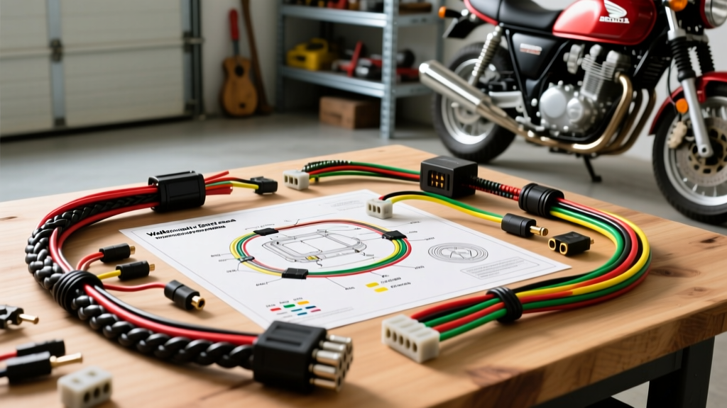
Introduction to the Simple Honda Motorcycle Wiring Diagram
When stripping down a classic Honda CB175, CB200, or CL350 for a cafe racer, scrambler, or tracker build, the factory harness often looks like an intimidating spaghetti nightmare. However, at its core, a simple Honda motorcycle wiring diagram is incredibly logical and standardized. Honda's engineering relies on a strict color-code system and predictable circuit routing that makes rewiring one of the most approachable tasks in the vintage motorcycle world. Whether you are deleting the airbox and battery tray for a custom loop or restoring a stock machine, understanding the fundamental flow of electricity from the stator to the spark plug is essential.
In this complete walkthrough, we will trace a simplified Honda twin-cylinder wiring diagram from the power source to the ground. We will cover specific wire color codes, American Wire Gauge (AWG) requirements, Sumitomo connector pinouts, and real-world troubleshooting tips to ensure your custom build starts on the first kick.
Phase 1: Tracing the Primary Power and Switchgear
Every simple Honda motorcycle wiring diagram begins at the battery and the main ignition switch. Unlike modern CAN-bus systems, vintage Hondas use a direct, analog switching method that is easy to test with a standard multimeter.
The Ignition Switch Pinout
The main ignition switch typically utilizes a 4-pin or 6-pin Sumitomo HM series connector. For a simplified custom harness, you generally only need to focus on two primary circuits:
- Red Wire (Battery Feed): This is your constant +12V DC power directly from the positive battery terminal. It should be routed through a main 15A or 20A inline fuse. Use 14 AWG wire for this main feed to prevent voltage drop.
- Black Wire (Switched Power): When the key is turned to the "ON" position, the Red wire bridges to the Black wire. The Black wire distributes switched +12V to the kill switch, headlight bucket, and fuse block for accessories.
Expert Tip: Always use a marine-grade fuse holder with a sealed O-ring. The Honda CB series is notorious for vibrating standard automotive blade fuse holders apart over time.
Phase 2: The Charging System and Rectifier Walkthrough
The charging system is where most custom builders make critical errors. A standard Honda twin utilizes a permanent magnet alternator (stator) that outputs raw, 3-phase Alternating Current (AC). This must be converted to Direct Current (DC) and regulated to prevent overcharging the battery.
Stator to Regulator/Rectifier Routing
The stator exits the left-side engine cover via a rubber grommet, typically terminating in a 3-pin or 4-pin JST or Sumitomo connector. The standard simple Honda wiring diagram color coding for the stator is:
- Yellow (x3): 3-Phase AC output for the lighting and charging circuit. These three wires are interchangeable when connecting to a modern aftermarket MOSFET Regulator/Rectifier.
- White or Pink: AC output dedicated to the ignition circuit (on points-based models) or a separate lighting coil.
When upgrading to a modern MOSFET unit (highly recommended over the old mechanical shunt regulators), you will use the three Yellow wires for the AC input. The DC output side of the regulator will feature a Red wire (+12V to battery) and a Green wire (Ground). Ensure the Red output wire is a minimum of 14 AWG and connects directly to the battery positive or the main starter solenoid stud, bypassing the ignition switch to ensure the battery always receives a charge.
For more information on upgrading vintage charging systems, consult the technical guides at Rick's Motorsport Electrics, which provide excellent bench-testing procedures for Honda stators.
Phase 3: Ignition Circuit and Coil Routing
The ignition circuit demands high voltage at the spark plug, but the primary side of the ignition coil only requires a standard low-voltage trigger. In a simple Honda motorcycle wiring diagram, the ignition circuit is isolated from the heavy-draw lighting circuits to ensure a strong spark at low RPMs.
Points vs. CDI Wiring
If your Honda utilizes a mechanical points plate (common on pre-1978 models like the CB175), the wiring is beautifully simple:
- Switched Power (+12V): A Black wire (or Black/White tracer) delivers switched power from the kill switch to the primary terminal of the ignition coil.
- Coil Ground/Trigger (-): The other primary terminal on the coil connects via a Black/Yellow wire directly to the mechanical points condenser and breaker arm inside the timing cover.
When the points open, the magnetic field in the coil collapses, inducing a high-voltage spike (up to 20,000 volts) through the secondary winding and out the spark plug wire. Use 18 AWG stranded copper wire for the primary coil feeds, and ensure you are using copper-core wires rather than modern carbon-core suppression wires, which can degrade the spark on vintage inductive coils.
Phase 4: Lighting, Horn, and Grounding Strategy
Honda's lighting circuits are generally AC-driven on the stator side in the simplest diagrams, meaning the headlight gets brighter as you rev the engine. However, for a reliable custom build, most builders convert the headlight to DC battery power.
The Honda Grounding Philosophy
In almost every simple Honda motorcycle wiring diagram, the Green wire is Ground. Unlike some European or American bikes that use the frame as the primary ground return for every component, Honda runs dedicated Green ground wires back to a central grounding point or directly to the battery negative terminal.
Crucial Warning: Do not rely solely on the motorcycle frame, engine mounts, and steering head bearings to act as your ground path. Rust, powder coating, and grease will create resistance. According to SAE J1128 standards for low-tension automotive wiring, voltage drop across a ground circuit should not exceed 0.1V under load. Always run a dedicated 12 AWG Green ground wire from the battery negative terminal to a clean, bare-metal bolt on the engine case, and use this as your main ground bus for all Green wires in the harness.
Honda Standard Wire Color & AWG Specification Chart
Use this reference table when crimping your new harness. Adhering to Honda's legacy color codes will make future troubleshooting significantly easier for you or any mechanic who works on the bike later.
| Wire Color | Function / Circuit | Recommended AWG | Connector Type |
|---|---|---|---|
| Red | Constant +12V Battery Power | 14 AWG | Sumitomo HM / Ring Terminal |
| Black | Switched +12V (Ignition ON) | 16 AWG | Sumitomo HM 090 |
| Green | System Ground (-) | 14 - 16 AWG | Sumitomo HM / Ring Terminal |
| Yellow | AC Stator Output (Lighting/Charge) | 16 AWG | JST / Sumitomo 250 |
| Black/Yellow | Ignition Coil Trigger (Points) | 18 AWG | Bullet / Spade |
| Blue / White | High Beam / Turn Signals | 18 AWG | Sumitomo HM 090 |
Expert Troubleshooting: Common Simple Diagram Failures
Even with a perfect diagram, physical execution can introduce faults. Here are the most common failure modes we see in custom Honda builds:
1. The "Dim Headlight at Idle" Issue
Symptom: The headlight pulses or stays dim until the engine is revved past 3,000 RPM.
Cause: The headlight is wired to the AC Yellow stator circuit instead of the DC Black switched circuit, or the battery is sulfated and failing to act as a capacitor for the system.
Fix: Rewire the headlight power feed to the Black (switched DC) wire, ensuring the headlight switch interrupts the DC feed, not the ground.
2. Weak Spark or Backfiring
Symptom: The bike backfires through the carbs or misfires under load.
Cause: Using a high-resistance carbon-core spark plug wire or a failing condenser on the points plate. Additionally, a poor ground at the ignition coil primary terminal will starve the coil of current.
Fix: Verify continuity from the coil mounting bracket to the battery negative. Replace carbon wires with copper-core 7mm suppression wires designed for vintage inductive systems. For OEM replacement diagrams and part numbers, cross-reference your VIN at CMSNL Honda Parts.
3. Blown Main Fuse Immediately
Symptom: The 15A main fuse pops the second the key is turned to "ON".
Cause: A pinched Black (switched power) wire shorting against the frame, or a failed horn button internally shorting to the handlebar.
Fix: Disconnect the horn and turn signal circuits. Use a multimeter in continuity mode to trace the Black wire from the ignition switch to the first junction. Wrap all harness sections passing through the steering neck with split-loom and friction tape to prevent chafing against the frame.
Final Thoughts on Harness Building
Building a harness from a simple Honda motorcycle wiring diagram is a rewarding process that eliminates the bulk and weight of 40-year-old degraded copper. Invest in a high-quality Sumitomo crimping tool (such as the HM-090/250 specific dies), use adhesive-lined marine heat shrink over every splice, and apply dielectric grease to all stator and regulator connectors. By respecting the AWG requirements and maintaining Honda's standardized color codes, you will create an electrical system that is as reliable as it is clean.