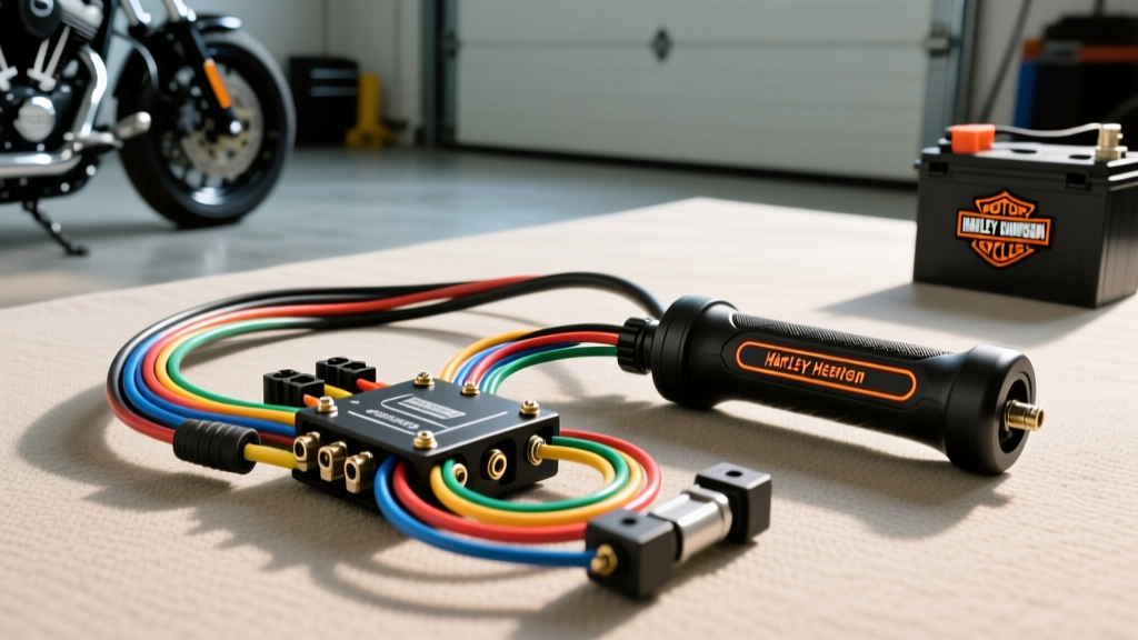
The Hidden Dangers in Your Harley Davidson Heated Grips Wiring Diagram
Installing aftermarket or OEM heated grips on a Harley-Davidson touring or cruiser model is one of the most popular cold-weather upgrades. However, consulting a generic Harley Davidson heated grips wiring diagram without understanding the specific current limitations and grounding nuances of the Milwaukee-Eight or Twin Cam electrical systems is a recipe for disaster. Heated grips typically draw between 3.5 to 4.5 amps per side, meaning a combined continuous load of up to 9 amps. When integrated improperly, this load can overwhelm accessory circuits, cause severe voltage drop, or create parasitic draws that leave you with a dead battery in freezing temperatures.
The Harley-Davidson charging system, particularly on older Twin Cam models, operates with a relatively narrow surplus amperage margin. According to Harley-Davidson Service Documentation, the stator output at idle is barely sufficient to run the ignition, fuel pump, and LED lighting. Adding a 9-amp resistive load like heated grips without proper relay switching and ignition-triggered isolation will quickly drain the battery or overheat the voltage regulator. This guide details the critical safety warnings, common wiring mistakes, and exact specifications required to safely integrate heated grips into your Harley's harness.
Critical Safety Warnings Before You Splice
1. The Powder-Coated Riser Grounding Trap
The most frequent cause of heated grip failure and melted wiring on Harley-Davidson motorcycles is an improper ground. Many riders attempt to ground the negative grip wire directly to the handlebar clamp bolts. However, Harley-Davidson handlebars and risers are often powder-coated or painted, and the riser mounts utilize rubber vibration-dampening bushings. This creates an electrically isolated circuit. If you ground to a powder-coated bolt, the current will seek the path of least resistance, often backfeeding through the throttle-by-wire sensor wiring or the handlebar switch housings, frying the BCM (Body Control Module). Always run a dedicated 14 AWG ground wire directly to the motorcycle frame or the negative battery terminal.
2. Battery Terminal Torque and Arcing Risks
When connecting your main power feed to the battery, hand-tightening the terminal bolts is a severe fire hazard. The vibration inherent to a V-Twin engine will loosen poorly torqued terminals, creating micro-arcing. This arcing generates intense localized heat, melting the battery post and potentially igniting hydrogen gas emitted by the battery. Always torque the main battery terminal bolts to exactly 95-105 in-lbs (8-9 ft-lbs) using a calibrated inch-pound torque wrench, and apply a dielectric grease over the terminal after tightening to prevent corrosion.
3. Wire Insulation Standards
Never use cheap, off-shore copper-clad aluminum (CCA) wire for high-draw accessories. You must use pure copper wire that meets SAE J1128 standards for Low Tension Primary Cable. SAE J1128 wire features cross-linked polyethylene (XLPE) insulation rated for 125°C, which is essential when routing wires near the Harley's rear exhaust header or the voltage regulator stator wires.
Common Wiring Mistakes & How to Fix Them
Mistake A: Bypassing the Relay (Direct-to-Battery Wiring)
The Error: Wiring the heated grip controller directly to the battery with an inline fuse, relying on the user to manually turn the grips off when parking.
The Consequence: Human error leads to a parasitic draw. A 9-amp draw will completely flatten a standard Harley 19Ah AGM battery in less than two hours, leaving you stranded.
The Fix: You must use a standard ISO Mini Relay (Bosch-style). The relay's heavy current circuit (Pins 30 and 87) should be wired directly to the battery (with a 15A fuse within 6 inches of the positive terminal). The trigger circuit (Pins 85 and 86) must be wired to a switched 12V source, such as the Harley accessory connector under the seat or the license plate light wire, ensuring the grips automatically shut off when the ignition is turned off.
Mistake B: Incorrect AWG Sizing for the Main Feed
The Error: Using 16 AWG or 18 AWG wire for the entire run from the battery to the handlebars.
The Consequence: Voltage drop. Heated grips require consistent voltage to generate heat. If you use 18 AWG wire for a 9-amp load over a 6-foot run, you will experience a voltage drop of nearly 1.5 volts. The grips will run lukewarm, and the wire insulation will become brittle and hot.
The Fix: Use 14 AWG stranded copper wire for the main feed from the battery to the relay, and from the relay to the handlebar area. Use 16 AWG wire only for the final short pigtail connections into the grips themselves.
Mistake C: Steering Neck Routing Without Slack Loops
The Error: Zip-tying the grip wires tightly along the existing harness through the steering neck.
The Consequence: When you turn the handlebars to full left or right lock, the wires stretch, snap internally, or slice open against the sharp metal edges of the frame neck, causing a dead short and a blown main fuse.
The Fix: Create a dedicated 'slack loop' or 'service loop' of at least 3 inches of wire just below the lower triple tree. Secure the wire with adhesive-lined heat shrink and P-clips, ensuring full lock-to-lock steering movement does not put tension on the harness.
Harley-Davidson Heated Grip Wiring Specifications Table
| Circuit Function | Harley OEM Wire Color | Required AWG Size | Fuse Rating | Connector / Pin Location |
|---|---|---|---|---|
| Main 12V Power Feed | Red (Aftermarket) | 14 AWG | 15A (ATC) | Battery Positive (+) |
| Main Ground Feed | Black (Aftermarket) | 14 AWG | N/A | Battery Negative (-) |
| Ignition Trigger (Switched 12V) | Orange/White Stripe | 18 AWG | 5A | Accessory Molex Pin 2 |
| Accessory Ground Trigger | Black | 18 AWG | N/A | Accessory Molex Pin 1 |
| Relay Load Output to Grips | Red/White (Heated Grip Kit) | 14 AWG | Protected by Main | Relay Pin 87 to Deutsch DT |
Step-by-Step Safe Routing & Connection Guide
- Disconnect the Battery: Always remove the negative (-) battery cable first and isolate it. Torque it back to 95-105 in-lbs upon completion.
- Mount the Relay: Secure the ISO mini relay under the seat or inside the fairing using a rubber isolation mount to protect it from V-Twin vibration. Ensure the relay pins face downward to prevent water ingress.
- Wire the Relay Trigger: Locate the Harley-Davidson accessory connector (usually a 6-pin Molex MX150 under the seat or side panel). Tap into Pin 2 (Orange/White) for the switched 12V trigger to Relay Pin 86. Ground Relay Pin 85 to Pin 1 (Black) or the frame.
- Wire the Heavy Circuit: Connect Relay Pin 30 to the positive battery terminal via a 15A inline ATC fuse holder. The fuse must be located within 6 inches of the battery post to protect the entire wire run.
- Install the Deutsch Connector: Do not hardwire the grips directly to the bike's harness. Crimp a 2-pin Deutsch DT plug onto the grip wires. This allows you to remove the handlebars or replace the grips in the future without cutting wires. Use the proper Deutsch wedge locks and crimp tool to prevent the pins from backing out.
- Test for Parasitic Draw: After reassembly, connect a multimeter in series with the negative battery cable. Turn the ignition off. The draw should read below 3mA. If it reads higher, your relay trigger wire is incorrectly tapped to a constant 12V source.
Diagnosing Voltage Drop with a Multimeter
If your heated grips are installed but fail to reach maximum temperature, do not immediately assume the heating elements are defective. Perform a voltage drop test. Set your multimeter to DC Volts. Place the red probe on the positive battery terminal and the black probe on the positive input terminal of the heated grip controller (with the grips turned on HIGH). A reading of more than 0.5 volts indicates excessive resistance in the positive wire run, usually caused by undersized wire, a corroded fuse holder, or a failing relay contact. Repeat the test on the ground side (black probe on battery negative, red probe on grip ground wire). For a deeper understanding of relay contact resistance and coil suppression, refer to the Littelfuse Automotive Relay Application Guide. Properly diagnosing these drops ensures your grips perform flawlessly in sub-freezing conditions.