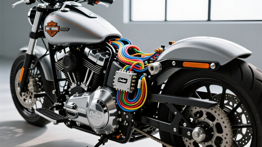
The Harley-Davidson Heritage Softail Classic (FLSTC) represents a unique intersection of classic cruiser aesthetics and evolving electrical engineering. From the Evolution (Evo) engines of the early 1990s to the Twin Cam 88B and subsequent Milwaukee-Eight platforms, the FLSTC wiring harness has grown from a simple analog network into a complex, data-integrated system. Sourcing accurate, free Harley-Davidson Heritage Softail wiring diagrams is critical for diagnosing parasitic draws, upgrading high-output stators, or installing auxiliary lighting without compromising the OEM data bus. This technical specification reference provides the exact pinouts, AWG requirements, and diagnostic baselines required for professional-level electrical troubleshooting on Heritage Softail models.
Twin Cam 88B Charging System Specifications
The charging system on the Twin Cam 88B Heritage Softail (2000-2017) relies on a three-phase, permanent-magnet stator paired with a shunt-style voltage regulator (VR). Unlike automotive alternators, the stator produces raw AC voltage that is rectified and regulated by the VR. The stator connector is a frequent failure point due to heat, vibration, and the ingress of road debris. When referencing wiring diagrams for the charging circuit, it is imperative to verify the wire gauge and terminal crimp integrity.
The stator outputs three phases of AC power. According to SAE International J1128 standards for automotive and motorcycle primary wire, the 14 AWG yellow wires used in the stator harness are rated for continuous high-temperature operation, but the OEM Molex or AMP connectors often degrade before the wire itself fails. Upgrading to a high-output stator (such as a 50-amp Lisle or Custom Chrome unit) requires upgrading the stator-to-VR harness to 12 AWG wire to prevent voltage drop and thermal melting at the connector block.
Stator to Voltage Regulator Pinout Matrix
| VR Connector Pin | Wire Color | AWG | Function / Destination | Diagnostic Baseline |
|---|---|---|---|---|
| 1 | Y (Yellow) | 14 | Stator Phase A | 19-26V AC per 1000 RPM (Pin-to-Pin) |
| 2 | Y (Yellow) | 14 | Stator Phase B | 19-26V AC per 1000 RPM (Pin-to-Pin) |
| 3 | Y (Yellow) | 14 | Stator Phase C | 19-26V AC per 1000 RPM (Pin-to-Pin) |
| 4 | BK (Black) | 14 | VR Chassis Ground | < 0.05 Ohms to Battery Negative |
| 5 | R/W (Red/White) | 14 | Switched Ignition 12V | 12.2V+ with Key ON, Engine OFF |
Note: Stator ground isolation is critical. A megohmmeter test between any yellow stator wire and the stator core should yield infinite resistance (>10 MΩ). Any reading below this indicates a short to ground, necessitating stator replacement.
Delphi EFI and Ignition Module Wiring Reference
In 2007, the Heritage Softail transitioned to the Delphi Electronic Fuel Injection (EFI) system, replacing the earlier Magneti Marelli setup. The Delphi ECM utilizes a 36-pin sealed connector. The ignition system operates via an Ion Sensing Knock Control module on later models, but earlier Twin Cam Delphi models utilize a traditional dual-fire or single-fire coil setup driven directly by the ECM or an external Ignition Control Module (ICM).
When troubleshooting stalling, misfires, or a no-start condition on a carbureted or early EFI Heritage Softail, verifying the ICM pinouts and coil primary/secondary resistance is mandatory. The OEM ignition coil primary resistance should measure between 1.5 and 2.5 ohms, while the secondary resistance (measured from the spark plug wire terminals to ground) should range from 10,000 to 15,000 ohms. For in-depth diagnostic procedures on Harley charging and ignition systems, Nightrider's HD Technical Archives remains an industry-standard reference for bench-testing OEM components.
Delphi ECM 36-Pin Critical Sensor Pinouts
- Pin 1 (R/W - Red/White, 18 AWG)
- Ignition Switched Power. Supplies 12V to the ECM logic board. A voltage drop here causes erratic fuel mapping and stalling.
- Pin 2 (BK - Black, 18 AWG)
- ECM Main Ground. Routes to the primary engine ground stud. Must be cleaned and torqued to 120 in-lbs.
- Pin 12 (O/W - Orange/White, 20 AWG)
- MAP (Manifold Absolute Pressure) Sensor Signal. 5V reference return. Voltage should sit at 4.8V KOEO (Key On Engine Off) at sea level.
- Pin 14 (BN/W - Brown/White, 20 AWG)
- IAT (Intake Air Temperature) Sensor Signal. Resistance drops as temperature rises (approx. 2.5k Ohms at 68°F).
- Pin 22 (GY/BK - Gray/Black, 20 AWG)
- Crank Position Sensor (CKP) Signal. Requires an oscilloscope to verify the 5V square wave pattern during cranking.
Lighting, CAN-Bus, and Accessory Power Integration
Later model Heritage Softails (2014+) introduced localized data buses and dedicated accessory connectors to simplify the installation of Tour-Paks, sissy bar lighting, and heated grips. The OEM 6-pin accessory connector, typically zip-tied under the seat pan or routed near the rear fender strut, provides a safe interface for auxiliary loads without splicing into the main lighting harness.
OEM 6-Pin Accessory Connector Pinout
| Pin | Wire Color | Function | Max Draw |
|---|---|---|---|
| 1 | R/W (Red/White) | Switched 12V Accessory Power | 5A (Fused) |
| 2 | BK (Black) | Chassis Ground | 10A |
| 3 | W/V (White/Violet) | Running Light / 5V Data Reference | 1A |
| 4 | W/GN (White/Green) | Brake Light Trigger | 3A |
| 5 | W/BN (White/Brown) | Left Turn Signal Trigger | 3A |
| 6 | W/O (White/Orange) | Right Turn Signal Trigger | 3A |
Warning: If installing LED auxiliary lighting that draws less than the OEM incandescent bulbs, you must install load equalizers or use a CAN-bus-compatible LED flasher module to prevent hyper-flashing and ECM fault codes.
Harness Routing and Connector Specifications
The Softail frame presents unique routing challenges compared to the Touring or Dyna platforms. The main harness runs through the frame backbone, exiting near the steering head and routing down the left side of the transmission. The most common failure mode in the Heritage Softail main harness is chafing where the harness passes through the steering neck grommet. Over time, steering movement wears through the loom, exposing the 16 AWG and 18 AWG wires to the steel frame, resulting in intermittent short circuits that blow the 15A ignition fuse.
Harley-Davidson utilizes specific connector families across the FLSTC platform:
- AMP Multilock / Molex MX150: Used for sealed ECM and sensor connections. Features secondary locking tabs (TPA) that must be depressed before extracting a pin.
- Deutsch DT Series: Used for high-current, high-vibration areas such as the voltage regulator and main power distribution blocks. Requires specific wedgelocks to secure the pins.
- Metri-Pack 150/280: Commonly found on lighting connectors and the ignition switch. Prone to terminal fretting corrosion if dielectric grease is not applied during assembly.
Diagnostic Decision Tree: Electrical Failure Modes
Use the following symptom-cause-fix matrix to rapidly isolate electrical faults on the Heritage Softail without resorting to unnecessary parts replacement.
Symptom 1: Battery Drains Overnight (Parasitic Draw)
- Cause A: Faulty Voltage Regulator internal diode bridge allowing AC ripple to backfeed to the battery.
- Fix: Disconnect the VR connector. Perform a multimeter current draw test. If draw ceases, replace the VR.
- Cause B: Aftermarket accessory wired directly to the battery bypassing the ignition switch.
- Fix: Reroute accessory power through the OEM Accessory Connector (Pin 1) or install a solid-state relay triggered by the R/W ignition wire.
Symptom 2: Engine Cranks but Will Not Start (No Spark)
- Cause A: Bank Angle Sensor (BAS) tripped or failed, cutting power to the ignition coil.
- Fix: Cycle the kill switch OFF/ON to reset the ECM. If no spark, test the BAS 5V reference and ground.
- Cause B: Main 30A Circuit Breaker internal resistance causing voltage drop under cranking load.
- Fix: Measure voltage across the breaker terminals during cranking. A drop greater than 0.5V indicates a failed breaker. Replace with an OEM 30A automotive resettable breaker.
Symptom 3: Intermittent Stalling at Operating Temperature
- Cause A: Crank Position Sensor (CKP) failing when hot due to internal coil expansion.
- Fix: Monitor CKP AC voltage output while the engine is hot and cranking. It must exceed 2.5V AC. Replace if below spec.
- Cause B: Ignition coil primary winding breaking down under thermal load.
- Fix: Measure primary resistance immediately after a stall event. If resistance spikes to infinite (open circuit), replace the coil assembly.
For further community-driven diagnostics and advanced tuning parameters, the Electrosport Industries Technical Library provides excellent supplementary data on upgrading OEM charging systems to handle the heavy electrical loads of modern touring accessories and heated gear.