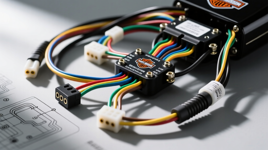
Introduction to Harley-Davidson Electrical Architecture
Decoding Harley Davidson wiring diagrams requires more than just tracing lines on a page; it demands a fundamental understanding of the motorcycle's electrical architecture. Modern Milwaukee-Eight (M8) Softail and Touring models utilize a complex Controller Area Network (CAN bus) system integrated with traditional high-current power distribution circuits. Whether you are troubleshooting a no-start condition, installing auxiliary lighting, or diagnosing a parasitic draw, the factory schematic is your ultimate roadmap. This complete wiring diagram walkthrough breaks down the main harness, power distribution, sensor pinouts, and common failure modes specific to late-model Harley-Davidson platforms.
How to Read the Grid System in HD Schematics
Harley-Davidson factory service manuals organize their schematics using an alphanumeric grid system. The vertical axis is labeled with letters (A, B, C) and the horizontal axis with numbers (1, 2, 3). This grid allows technicians to quickly locate specific components, such as the Bank Angle Sensor (BAS) or the Turn Signal Security Module (TSSM).
Furthermore, HD diagrams utilize specific symbol nomenclature:
- Splices (S): Denoted by a solid black dot where wires intersect. A factory splice is usually ultrasonically welded and sealed.
- Connectors (C): Labeled with a 'C' followed by a number (e.g., C145). The diagram will show the male (pin) and female (socket) halves separated for clarity.
- Grounds (G): Labeled with a 'G' (e.g., G201). The schematic will indicate the physical chassis location, which is critical for diagnosing voltage drop issues.
Step-by-Step Walkthrough: M8 Softail Main Harness
Power Distribution and Main Grounds
The journey of electrical current begins at the battery. In the M8 Softail platform, the main positive battery cable (typically 4 AWG or 2 AWG, Red) routes directly to the Main Circuit Breaker, usually located under the seat or side cover. From the breaker, a 10 AWG Red wire feeds the Ignition Switch.
When the key is turned to the 'ON' position, the ignition switch routes switched 12V power (Red/White wire, 14 AWG) to the Run/Stop Relay coil and the main fuse block. A critical point of failure here is the ignition switch connector itself; vibration and moisture ingress can cause terminal fretting corrosion, leading to a voltage drop that starves the Electronic Control Module (ECM) of adequate operating voltage.
Stator and Voltage Regulator Integration
Harley Davidson wiring diagrams dedicate a specific section to the charging system. The stator outputs 3-phase Alternating Current (AC) via three Yellow wires (typically 14 AWG). These route to the Voltage Regulator (VR). Unlike older Evolution or Twin Cam models that used a standard plug, modern M8 models often utilize high-amperage Deutsch DT series connectors or direct bolt-ring terminals to handle the 45+ amp output without melting. The VR converts the AC to DC, sending it back to the battery via a heavy-gauge Red wire, while the Black wire grounds to the engine case.
ECM Pinout and CAN Bus Data Lines
The heart of the M8 fuel injection system is the Delphi-sourced ECM. Understanding the ECM connector is vital for diagnosing sensor faults. Modern Harley Davidson wiring diagrams highlight the CAN bus lines, which allow the ECM, ABS module, and speedometer to communicate without running individual wires for every signal.
Below is a reference table for the primary 35-pin ECM connector (Delphi Metri-Pack 280 series) commonly found on M8 Softail models:
| Pin Number | Wire Color | AWG | Function / Circuit Description |
|---|---|---|---|
| 1 | Green/Yellow | 20 | CAN-High (Data Link to ABS/Speedo) |
| 2 | Green/Orange | 20 | CAN-Low (Data Link to ABS/Speedo) |
| 7 | Red/White | 18 | Switched 12V Ignition Power |
| 15 | Black | 14 | Main ECM Chassis Ground |
| 22 | Gray | 20 | Vehicle Speed Sensor (VSS) Signal |
| 28 | Orange/White | 18 | Front Injector Low-Side Driver |
Note: Pinouts vary slightly by exact model year and California (CARB) vs. 49-State emissions calibrations. Always cross-reference with the specific year's factory manual.
Diagnosing Common Harness Failure Modes
The 'Burnt Stator Plug' Phenomenon
While Harley-Davidson has improved their charging system connectors, older Twin Cam and early Softail models are notorious for melting the 3-pin stator-to-regulator plug. The diagram shows these as three Yellow wires. The failure mode is caused by high resistance at the crimp terminals due to vibration and thermal cycling. When diagnosing a 'no-charge' condition, do not just check the VR. Back-probe the stator plug while the engine is running at 3,000 RPM. You should read 40-70 VAC between any two yellow wires. If you read battery voltage (DC) or significantly lower AC voltage on one leg, the stator or the connector is compromised. The industry-standard repair is to cut off the OEM plug and solder the connections, sealing them with adhesive-lined dual-wall heat shrink.
Voltage Drop Testing the Main Power Circuit
A multimeter set to DC Volts is your best tool for reading between the lines of a wiring diagram. If your M8 Softail cranks slowly but the battery tests at 12.8V, perform a voltage drop test:
- Connect the multimeter's red probe to the battery positive post and the black probe to the ECM main power input (Pin 7).
- Turn the ignition ON and crank the engine.
- A healthy circuit should show a voltage drop of less than 0.5V total. If you see a 1.5V drop, you have high resistance in the Red/White 18 AWG wire, likely at the Run/Stop relay contacts or the ignition switch.
Repair Standards and Best Practices
When modifying or repairing a Harley-Davidson harness, adhering to automotive electrical standards is non-negotiable. According to the SAE J1128 standard for low-tension primary cable, wire insulation must withstand under-hood temperatures and chemical exposure. Never use generic household wire; always use SAE J1128 compliant cross-linked polyethylene (XLPE) or PVC automotive primary wire.
Furthermore, when splicing wires or repairing a broken pin in a Delphi Metri-Pack connector, follow the IPC/WHMA-A-620 wiring harness assembly guidelines. This dictates that all solder joints must be mechanically secured before soldering, and all exterior splices must be sealed with marine-grade, adhesive-lined heat shrink to prevent capillary action from drawing moisture into the harness. Electrical tape is strictly prohibited for permanent harness repairs, as the adhesive degrades under engine heat and vibrates loose, exposing the copper to rapid oxidation.
Conclusion
Mastering Harley Davidson wiring diagrams transforms a daunting web of colored wires into a logical, traceable system. By understanding the alphanumeric grid, respecting the CAN bus architecture, and applying rigorous voltage-drop testing methodologies, you can accurately diagnose and repair even the most elusive electrical gremlins on your Softail, Touring, or Sportster platform.