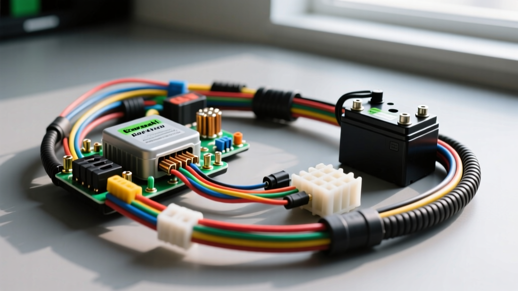
Understanding the Kawasaki 220 Bayou Electrical Architecture
When diving into powersports electrical repair, the Kawasaki 220 Bayou wiring diagram is one of the most forgiving and educational blueprints a beginner can study. Produced from 1988 through 2002, the KLF220 Bayou represents an era of minimalist, robust ATV engineering. Unlike modern quads burdened with complex CAN-bus networks, EFI systems, and digital dashboards, the Bayou 220 relies on a straightforward, split-system electrical layout. For novice mechanics and DIY enthusiasts, understanding this harness is the perfect gateway into mastering motorcycle and ATV electrical diagnostics.
The KLF220 electrical system is fundamentally divided into two distinct circuits: the AC generation and ignition circuit (which operates independently of the battery) and the DC accessory and starting circuit (which relies on the 12V battery). By separating these systems, Kawasaki ensured that a dead battery would never leave a rider stranded in the woods, provided the engine could be pull-started or bump-started.
The AC-CDI System: Why Your Bayou Sparks Without a Battery
One of the most critical fundamentals to grasp when reading a Kawasaki 220 Bayou wiring diagram is the operation of the AC-powered Capacitor Discharge Ignition (AC-CDI). Many beginners mistakenly believe the CDI unit draws power from the 12V battery to create a spark. On the KLF220, this is false.
The CDI unit receives its primary voltage directly from the stator's exciter coil. As the flywheel magnets pass over the exciter coil, it generates a high-voltage AC pulse (often between 100V and 400V AC). This pulse is routed directly to the CDI box, where it is stored in a capacitor and then discharged into the ignition coil precisely when the pickup coil signals the correct timing. Because the ignition system is entirely self-sustaining, you can completely disconnect the battery on a Bayou 220, pull the recoil starter, and the engine will fire right up.
Kawasaki 220 Bayou Wiring Diagram: Master Color Code Table
Kawasaki utilizes a highly standardized color-coding system across its vintage and retro powersports lineup. When tracing faults in your harness, identifying these primary wire colors will save you hours of multimeter probing. Below is the definitive color code reference for the KLF220 harness.
| Wire Color | Function / Circuit | System Type | Diagnostic Notes |
|---|---|---|---|
| Red | Main Battery Positive (+12V DC) | DC System | Hot at all times. Check for voltage drops at the main fuse. |
| Black | Chassis Ground | DC / AC | Must have less than 0.1 ohm resistance to the battery negative terminal. |
| White | Stator Lighting Coil Output (AC) | AC System | Routes to the Regulator/Rectifier. Outputs 30-60V AC at high RPM. |
| Black/Red | Stator Exciter Coil Output | AC Ignition | Supplies primary voltage to the CDI. Do not confuse with DC power. |
| Black/Yellow | Ignition Kill Circuit | AC Ignition | When grounded to the chassis, it shorts the CDI and stops the spark. |
| Brown | Tail Light / Marker Lights | DC System | Switched 12V DC from the ignition/lighting switch. |
| Gray | Left Turn Signal / Indicator | DC System | Pulsed 12V DC from the flasher relay. |
| Green | Right Turn Signal / Indicator | DC System | Pulsed 12V DC from the flasher relay. |
| Blue/Yellow | Starter Solenoid Trigger | DC System | Carries 12V from the starter button to the relay coil. |
Stator and Regulator/Rectifier Fundamentals
The stator on the Kawasaki Bayou 220 is a dual-purpose component hidden behind the left-side engine cover. It houses both the lighting coil (for charging the battery and running lights) and the exciter coil (for the CDI). Because the lighting coil produces raw Alternating Current (AC), it must be converted to Direct Current (DC) and regulated to prevent overcharging the 12V lead-acid battery.
This is where the Regulator/Rectifier comes in. The Bayou 220 typically uses a simple single-phase or half-wave rectifier unit. It takes the raw AC from the White stator wire, converts it to DC using internal diodes, and shunts excess voltage to ground to maintain a steady 13.8V to 14.4V DC output. A common failure mode on older KLF220 models is a burnt-out rectifier diode, which results in AC voltage leaking into the DC harness. This will cause headlights to blow out at high RPMs and rapidly boil the battery acid. Always test your battery terminals with a multimeter set to AC Voltage while the engine is revving; if you read more than 1.0V AC, your regulator/rectifier has failed.
Step-by-Step No-Spark Troubleshooting Tree
When your Bayou 220 cranks but refuses to start, the issue is almost always within the AC ignition circuit. Follow this beginner-friendly decision tree to isolate the fault without throwing expensive parts at the problem.
- Symptom: Engine cranks, but no spark at the plug.
- Step 1: Check the Kill Circuit (Black/Yellow Wire).
- Disconnect the main harness plug near the CDI.
- Test for continuity between the Black/Yellow wire and the chassis ground.
- Result: If there is continuity with the key ON and the kill switch in the 'Run' position, you have a shorted kill switch, a bad key cylinder, or a pinched wire in the steering stem. The CDI thinks you are turning the bike off.
- Step 2: Test the Stator Exciter Coil (Black/Red Wire).
- Set your multimeter to Ohms (Ω).
- Measure resistance between the Black/Red stator wire and the engine case ground.
- Result: A healthy KLF220 exciter coil should read between 90 and 150 ohms. If it reads infinite (open) or near zero (shorted), the stator must be replaced.
- Step 3: Test the Pickup Coil (Pulsar).
- Measure the resistance across the pickup coil wires (usually White/Red and White/Blue).
- Result: Specification is typically 360 to 540 ohms. A failed pickup coil will not send the timing signal to the CDI, resulting in zero spark.
- Step 4: Verify the Ignition Coil and CDI.
- If the stator and pickup coil test perfectly, and the kill circuit is not grounded, the CDI unit or the high-tension ignition coil is faulty. Swap with a known-good OEM CDI to confirm.
- Step 1: Check the Kill Circuit (Black/Yellow Wire).
Wire Gauge (AWG) and Connector Specifications for Repairs
When repairing a damaged Kawasaki 220 Bayou wiring harness, using the correct wire gauge and connectors is paramount for fire safety and voltage delivery. According to SAE J1128 standards for low-tension primary cables, powersports wiring must withstand high engine bay temperatures and severe vibration. Never use standard household copper wire; always use stranded, cross-linked polyethylene (XLPE) or PVC automotive primary wire.
| Circuit Type | Recommended AWG | Connector Type |
|---|---|---|
| Starter Motor & Battery Main | 10 AWG or 8 AWG | Ring Terminals (6mm / 1/4 inch) |
| Main Harness Power / Regulator | 14 AWG | Sumitomo HM 090 Series / Vinyl Bullets |
| Lighting, Tail, and Dash | 18 AWG | 2.8mm Male/Female Spade Connectors |
| Stator to Regulator/Rectifier | 16 AWG | 2.8mm Rubber Bullet Connectors |
Pro-Tip for Stator Connectors: The rubber bullet connectors where the stator exits the engine case are notorious for collecting water and corroding. When rebuilding a KLF220 harness, pack these bullet connectors with dielectric grease and wrap the junction in self-amalgamating silicone tape to create a waterproof seal. For permanent harness repairs, avoid crimp-only butt connectors; use a solder-seal heat shrink connector to ensure a gas-tight, vibration-proof bond.
Authoritative Resources & Further Reading
To continue your journey into powersports electrical diagnostics, always refer to factory documentation and established industry standards. The following resources are invaluable for ATV and motorcycle wiring repair:
- Kawasaki Owner & Service Manuals: Always consult the official Kawasaki Manuals Portal for your specific VIN year to verify exact torque specs and routing diagrams.
- Stator & CDI Testing Guides: For advanced multimeter diagnostics on AC-CDI systems and 3-phase stators, the Ricky Stator Testing Guide provides excellent baseline procedures applicable to the Bayou 220.
- SAE Wiring Standards: Familiarize yourself with SAE J1128 and SAE J1292 to ensure your custom repairs meet automotive fire-safety requirements.
By mastering the fundamentals of the Kawasaki 220 Bayou wiring diagram, you build a diagnostic foundation that will serve you across almost all vintage and carbureted motorcycles, ATVs, and side-by-sides. Take your time, trust your multimeter, and always verify your grounds.