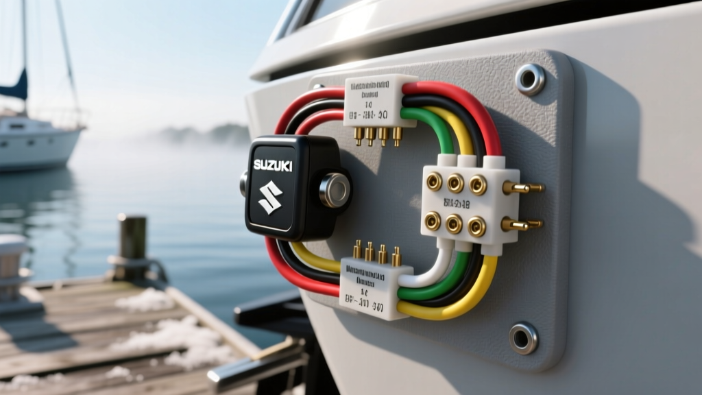
Introduction to Suzuki DF Ignition Systems
Upgrading or replacing the ignition switch on a Suzuki four-stroke outboard requires a precise understanding of the marine electrical system. Whether you are rigging a new center console or troubleshooting a no-start condition on a Suzuki DF140, DF150, or DF200, the ignition switch acts as the central command for the Engine Control Module (ECM), starter solenoid, and magneto kill circuit. Relying on an accurate Suzuki outboard key switch wiring diagram is critical to prevent catastrophic short circuits, ECM damage, or being stranded on the water. Unlike older two-stroke engines that simply grounded the ignition coil, modern Suzuki EFI outboards require clean, uninterrupted 12V DC power to the ECM and fuel pump relays. This practical installation guide details the exact pin configurations, ABYC-compliant wire sizing, and step-by-step procedures to correctly wire a Suzuki marine ignition switch.
Suzuki Outboard Key Switch Wiring Diagram and Pinout
The standard Suzuki marine ignition switch (commonly part number 34820-90510 or equivalent 6-pin universal marine switch) utilizes a specific terminal layout. Understanding these terminal designations is the first step in interpreting the Suzuki outboard key switch wiring diagram. Below is the definitive pinout reference for the rear terminals of the switch.
| Terminal ID | Function | Suzuki Harness Wire Color | Recommended AWG | Switch Position Active |
|---|---|---|---|---|
| B | Battery (Main 12V+ Input) | Red | 10 AWG | OFF, ON, START |
| I | Ignition (ECM & Fuel Pump Power) | Yellow | 14 AWG | ON, START |
| S | Start (Starter Solenoid Trigger) | White with Red Stripe | 12 AWG | START (Spring Return) |
| M | Magneto / Kill (ECM Ground Stop) | Black with Yellow Stripe | 14 AWG | OFF (Grounds to M) |
| G | Ground (Switch Illumination / Reference) | Black | 14 AWG | Always (for 12V- return) |
| L | Light / Accessory (Panel Illumination) | Blue | 16 AWG | ON, START |
When referencing the Suzuki Marine Parts and Accessories documentation, note that the 'M' terminal is critical for engine shutdown. When the key is turned to the OFF position, the switch internally bridges the 'M' and 'G' (or 'B-') terminals, sending a ground signal to the ECM stop wire. If this wire is disconnected or broken, the engine will continue to run even when the key is removed.
ABYC E-11 Compliance and Wire Sizing
Marine environments demand strict adherence to the ABYC E-11 AC & DC Electrical Systems on Boats standard. Voltage drop is the enemy of modern EFI outboards. The Suzuki ECM requires a minimum of 10.5V during cranking to fire the injectors. If your wire run from the battery to the helm, and then to the engine harness, exceeds 15 feet, you must increase the wire gauge to compensate for resistance.
- Main Battery Feed (B Terminal): Use 10 AWG tinned marine copper wire for runs up to 15 feet. For runs exceeding 15 feet, step up to 8 AWG to ensure maximum current delivery to the 'I' and 'S' circuits.
- Starter Solenoid Trigger (S Terminal): 12 AWG is standard, but the inrush current to the solenoid relay can spike. Ensure the inline fuse on the main 'B' feed is rated for 30A to protect the switch contacts.
- ECM Ignition Feed (I Terminal): 14 AWG tinned wire is sufficient, protected by a 5A or 10A inline fuse. The ECM draws very little amperage directly through the key switch; it primarily triggers the main EFI relay.
Always use UL 1426 or SAE J1171 rated boat cable. Standard automotive copper wire will oxidize rapidly in a saltwater environment, leading to high-resistance connections and intermittent starting failures.
Required Tools and Marine-Grade Materials
Before beginning the installation, gather the following specialized marine electrical tools and materials:
- Suzuki 6-pin ignition switch and matching rubber weather boot.
- Ancor or 3M Marine adhesive-lined heat shrink terminals (ratcheting crimp tool required).
- Wire strippers calibrated for 10, 12, 14, and 16 AWG marine stranded wire.
- Digital multimeter (DMM) capable of measuring DC voltage and continuity.
- Non-contact voltage tester and terminal insertion pick tool.
- Dielectric grease (e.g., NO-OX-ID A-Special) for terminal corrosion prevention.
- Zip ties, split loom tubing, and cable clamps for ABYC-compliant routing.
Step-by-Step Key Switch Installation Guide
Follow these precise steps to install and wire your Suzuki outboard key switch safely and effectively.
- Isolate the DC Power Source: Disconnect the negative battery terminal at the transom battery bank. Verify zero voltage at the helm using your DMM before cutting or stripping any wires.
- Prepare the Helm Cutout: Ensure the dashboard hole is exactly 2-1/16 inches (52mm) in diameter. Clean the area with isopropyl alcohol to ensure the rubber O-ring on the switch housing seals completely against the fiberglass or aluminum console.
- Crimp and Seal the Terminals: Strip 3/8 inch of insulation from your marine-grade wires. Insert the wire into the adhesive-lined heat shrink barrel of the female spade terminal. Crimp using a ratcheting tool, then apply heat evenly until the adhesive oozes from the edges. This creates a waterproof seal mandated by marine electrical standards.
- Wire the 'B' and 'I' Terminals: Connect the 10 AWG Red wire to the 'B' terminal and the 14 AWG Yellow wire to the 'I' terminal. Apply a microscopic dab of dielectric grease to the male spades on the switch before pushing the female connectors on. You should hear a distinct click.
- Wire the 'S' and 'M' Terminals: Attach the 12 AWG White/Red wire to 'S' and the 14 AWG Black/Yellow wire to 'M'. The 'M' wire must route directly to the corresponding Black/Yellow pin on the Suzuki main engine harness connector. Do not splice this into a generic ground bus; it must communicate directly with the ECM kill circuit.
- Secure the Switch to the Console: Slide the switch through the cutout, place the dress nut and locking washer over the front bezel, and tighten using a spannel wrench. Torque to 15-20 in-lbs. Do not overtighten, as this will crack the bakelite housing and compromise the internal waterproof seals.
- Test Voltage Drop and Continuity: Reconnect the battery. With the key OFF, test continuity between 'M' and 'G' (should be near 0 ohms). Turn the key to ON; test voltage between 'I' and ground (should read battery voltage, minus a maximum 3% voltage drop). Turn to START; verify 12V at the 'S' terminal.
Real-World Troubleshooting: Symptom-Cause-Fix
Even with a perfect Suzuki outboard key switch wiring diagram, installation errors or harness degradation can cause operational faults. Use this decision tree to diagnose common issues.
| Symptom | Probable Cause | Diagnostic Fix |
|---|---|---|
| Engine cranks but will not start. | No 12V reaching the ECM via the 'I' terminal. Fuel pump relay not engaging. | Probe the Yellow wire at the engine harness with a DMM while key is ON. If 0V, check the inline fuse and 'I' terminal crimp. |
| Turns key to START, only a single click is heard, no crank. | Voltage drop across the 'S' terminal or failing starter solenoid. | Measure voltage at the White/Red wire at the solenoid during crank attempt. If below 9.5V, upgrade wire gauge or clean battery ground. |
| Engine runs perfectly but will not shut off when key is turned to OFF. | 'M' terminal kill circuit is open. ECM is not receiving the ground signal. | Check continuity of the Black/Yellow wire from the switch 'M' terminal to the engine harness. Repair any broken splices. |
| Switch feels hot to the touch after 30 minutes of running. | High resistance on the 'B' terminal due to a poor crimp or undersized wire. | Perform an infrared thermal scan or voltage drop test across the 'B' terminal. Re-crimp using adhesive-lined terminals. |
Authoritative References
For further technical validation and advanced marine electrical theory, consult the following resources:
- ABYC E-11 AC & DC Electrical Systems on Boats - The definitive standard for marine wire sizing, overcurrent protection, and voltage drop limits.
- Suzuki Marine Parts and Accessories - Official OEM part numbers, harness routing diagrams, and ECM pinout references for DF series outboards.
- Marine How To Electrical Guides - Excellent practical tutorials on adhesive heat shrink crimping and marine switchgear maintenance.
By strictly following this Suzuki outboard key switch wiring diagram and adhering to marine-grade installation practices, you ensure reliable starts, safe ECM operation, and compliance with federal and ABYC safety standards. Always double-check your wire colors against your specific model year's service manual, as aftermarket harness adapters may utilize non-standard color codes.