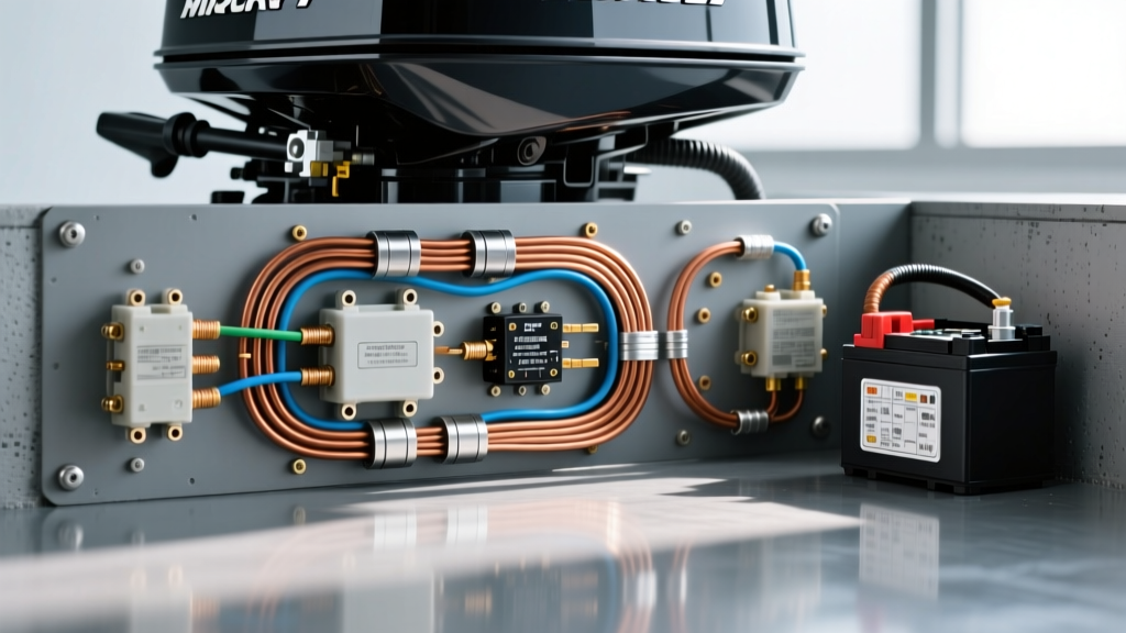
The Hidden Dangers in the 90 HP Mercury Outboard Wiring Diagram
Rigging a boat is not like wiring a car. When marine technicians and DIY enthusiasts consult a 90 HP Mercury outboard wiring diagram, they often assume that standard automotive electrical principles will suffice. This assumption is the root cause of catastrophic electrical fires, stranded vessels, and thousands of dollars in fried Electronic Control Units (ECUs). The marine environment is inherently hostile, characterized by high humidity, salt spray, and constant vibration. A 90 HP Mercury outboard—whether it is a 4-stroke EFI or a 2-stroke OptiMax—relies on a precise, low-resistance electrical network to manage fuel injection, ignition timing, and alternator output. Misinterpreting the wiring schematic or taking shortcuts with materials will inevitably lead to failure. This guide outlines the most dangerous wiring mistakes and critical safety warnings you must heed when rigging or troubleshooting a Mercury 90 HP outboard.
Mistake #1: Using Automotive Wire (SAE J1128) Instead of Marine (SAE J378)
The most frequent and destructive mistake found in amateur rigging is the use of standard automotive copper wire. Automotive wire is manufactured to SAE J1128 standards, which utilize bare copper strands. In a marine environment, moisture and salt penetrate the wire jacket and react with the bare copper, creating copper oxide (the notorious 'green powder'). This corrosion increases electrical resistance, generates excessive heat, and causes severe voltage drops.
More dangerously, bare copper is susceptible to capillary action. If a wire terminal is exposed to bilge water, the water will wick up inside the wire insulation, traveling feet away from the source and corroding connections behind the dashboard. You must exclusively use marine-grade wire compliant with SAE J378 standards. This wire features individually tinned copper strands that resist oxidation and block capillary wicking. Furthermore, all connections must be sealed using adhesive-lined, dual-wall heat shrink terminals to create a watertight barrier.
Warning #1: The EFI Voltage Drop Trap and Starter Circuit Sizing
Modern Mercury 90 HP 4-stroke EFI engines draw significant current during cranking, often exceeding 180 amps. A critical safety warning found in factory service manuals is the risk of ECU reset due to voltage drop. If the voltage at the main harness drops below 10.5V while the starter is engaged, the ECU will brown out and reboot. The engine will crank endlessly but never fire, leading owners to mistakenly blame the fuel pump or ignition coils.
The Fix: The main battery cables running from the battery switch to the engine starter solenoid and ground block must be a minimum of 2/0 AWG for runs up to 15 feet. If the run exceeds 15 feet, you must step up to 4/0 AWG. Never use 4 AWG or 6 AWG wire for the main starter circuit on a 90 HP outboard, regardless of what the physical terminal size on older aftermarket solenoids might suggest. Always measure voltage drop across the positive and negative cables simultaneously while cranking; the combined drop must not exceed 3% (approximately 0.36V on a 12V system).
Mistake #2: Miswiring the 14-Pin Main Harness Connector
The modern Mercury 90 HP outboard utilizes a 14-pin main harness connector to interface with the helm controls, ignition switch, and gauges. Cross-wiring these pins or using undersized wire for the harness can result in melted connectors or erratic gauge behavior. Below is the standard pinout reference and the most common rigging errors associated with each.
| Pin | Wire Color | Function | Common Rigging Mistake & Hazard |
|---|---|---|---|
| 1 | Red | 12V Battery (Constant) | Using 14 AWG instead of 10 AWG. Causes voltage drop to gauges and memory loss in digital tachometers. |
| 2 | Purple | Ignition (Switched 12V) | Tying into a high-draw accessory circuit. ECU starves for power when bilge pumps activate. |
| 3 | Yellow | Starter Solenoid Trigger | Bypassing the neutral safety switch. Engine can start in gear, causing severe prop-strike injuries. |
| 4 | Black | Main Ground | Grounding to a painted hull surface or shared accessory block instead of the dedicated engine block stud. |
| 5 | Black/Yellow | Magneto Short / Kill | Wiring to a switched positive. The kill circuit MUST ground to stop the engine; positive voltage will fry the CDI/stator. |
| 6 | Dark Blue | Trim Up | Reversing polarity with Trim Down. Causes trim relay chatter and premature hydraulic pump failure. |
| 7 | Light Blue | Trim Down | Using non-waterproof spade connectors at the helm switch, leading to corrosion-induced continuous trim-down. |
| 8 | White | Choke / Warm-up | Leaving connected on EFI models where it is obsolete, causing idle speed anomalies. |
Warning #2: The 'Load Dump' Rectifier Destroyer
One of the most expensive mistakes a boat owner can make is disconnecting the battery while the Mercury 90 HP outboard is running. Unlike automotive alternators with robust internal suppression, marine stators and rectifier/voltage regulators rely on the battery as a massive capacitor to absorb voltage spikes. If the battery connection is severed (or if a battery switch is accidentally bumped to 'OFF' while on plane), the stator will experience a 'load dump'. Voltage can instantly spike to 50V or higher, instantly vaporizing the rectifier diodes, frying the ECU, and blowing out every incandescent bulb and digital gauge on the vessel. Always install a prominent warning label near the battery switch: 'NEVER DISCONNECT BATTERY WHILE ENGINE IS RUNNING.'
Troubleshooting Decision Tree: Electrical Gremlins & No-Starts
When your 90 HP Mercury fails to start or exhibits erratic electrical behavior, use this symptom-cause-fix decision tree before replacing expensive components like the stator or ECU.
- Symptom: Engine cranks slowly, ECU resets, gauges flicker.
Cause: High resistance in the main ground or positive cable.
Fix: Perform a voltage drop test on the 2/0 AWG cables. Clean the engine block ground stud with a wire brush to bare metal. Torque the ground nut to 120 in-lbs and coat with dielectric grease. - Symptom: Engine will not crank, solenoid clicks rapidly.
Cause: Neutral safety switch misalignment or corroded Yellow trigger wire.
Fix: Check for 12V at the Yellow wire (Pin 3) at the engine harness while turning the key to 'START'. If absent, adjust the shift linkage detent at the helm binnacle. - Symptom: Engine runs, but battery voltage climbs past 15.5V, boiling the battery.
Cause: Failed voltage regulator or broken sense wire.
Fix: Inspect the Red sense wire running from the regulator to the starter solenoid. If the sense wire loses connection, the regulator defaults to maximum output. Repair the sense wire with an adhesive-lined butt splice. - Symptom: Lanyard kill switch fails to stop the engine.
Cause: Broken Black/Yellow wire or corroded helm switch contacts.
Fix: Disconnect the main harness. Use a multimeter to test continuity between Pin 5 (Black/Yellow) and Pin 4 (Black/Ground) while pulling the lanyard. If continuity is absent, replace the helm kill switch assembly.
Authoritative Marine Electrical Standards
Proper rigging requires adherence to established marine engineering standards. For comprehensive guidelines on overcurrent protection, wire sizing, and battery isolation, refer to the ABYC E-11 AC and DC Electrical Systems on Boats standard. Additionally, the National Marine Manufacturers Association (NMMA) provides certification requirements that mandate the use of tinned copper wire and proper ignition-protected components in enclosed bilge areas. Always cross-reference your specific engine serial number with the official Mercury Marine service manual, as pinouts and ECU requirements can vary slightly between the Carbureted, EFI, and Command Thrust variations of the 90 HP platform.