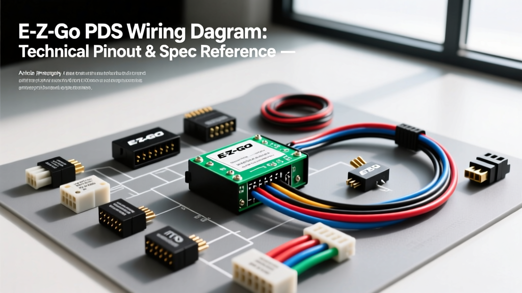
Architecture of the E-Z-GO Precision Drive System (PDS)
The E-Z-GO Precision Drive System (PDS) represents a landmark era in electric golf cart engineering, predominantly utilized in TXT and Freedom chassis from 1996 through 2011. Unlike older series-wound resistor-based speed controls, the PDS relies on a solid-state motor speed controller paired with a Separately Excited (Sepex) DC motor. This architecture enables advanced features such as regenerative braking, electronic speed limiting, and multi-mode drive profiles (e.g., Freedom mode for higher top speed). Understanding the ezgo pds wiring diagram requires a bifurcated approach: analyzing the high-current traction circuit and the low-voltage logic harness. This technical reference provides the exact pinout matrices, wire gauge requirements, and diagnostic parameters required for professional-grade troubleshooting and harness reconstruction.
High-Current Power Circuit & AWG Specifications
The traction circuit in a 48V PDS system carries immense amperage, frequently peaking above 300A during heavy loads or steep inclines. Adhering to proper wire gauge and crimping standards is critical to prevent voltage drop, thermal runaway, and connector melting. According to SAE J1128 standards for low-tension primary cables, automotive-grade copper with high-strand counts must be used to withstand the constant vibration of the cart chassis.
| Circuit Path | Recommended AWG | Terminal Type | Torque Specification |
|---|---|---|---|
| Battery Pack Positive to Solenoid | 2 AWG | 3/8' Ring Terminal (Heat Shrink) | 120 in-lbs |
| Solenoid to Controller B+ Stud | 2 AWG | 3/8' Ring Terminal | 140 in-lbs |
| Controller B- to Motor A1 | 2 AWG | 3/8' Ring Terminal | 120 in-lbs |
| Motor A2 to Main Negative Bus | 2 AWG | 3/8' Ring Terminal | 120 in-lbs |
| Controller S1/S2 to Motor Field | 6 AWG | 5/16' Ring Terminal | 80 in-lbs |
Expert Note: Never use solid-core wire or standard hardware store battery cables for the high-current loop. You must use fine-strand, high-flex welding cable or marine-grade tinned copper to prevent internal strand fracturing near the motor mounts.
E-Z-GO PDS Controller Pinout Matrix
The PDS controller interfaces with the cart's logic systems via a primary 10-pin harness connector. This connector carries the 48V logic feed, sensor inputs, and solenoid activation signals. When referencing an ezgo pds wiring diagram, verifying the integrity of these specific pins is the first step in diagnosing a 'dead pedal' condition.
| Pin | Wire Color | Function / Destination | Operating Voltage / State |
|---|---|---|---|
| 1 | Red | Key Switch Input (B+) | 48V (Key ON) |
| 2 | Blue | Solenoid Coil Output | Pulls to Ground to engage |
| 3 | Yellow | F/R Switch (Forward Input) | 48V (FWD Selected) |
| 4 | Black/Yellow | F/R Switch (Reverse Input) | 48V (REV Selected) |
| 5 | Yellow | ITS Sensor (Signal/Coil High) | Varying AC/Resistance |
| 6 | White | ITS Sensor (Ground/Coil Low) | Sensor Return |
| 7 | White/Red | Run/Tow Switch Input | 48V (Run) / Open (Tow) |
| 8 | Orange | Foot Brake Microswitch | 48V (Pedal Depressed) |
| 9 | Brown | Reverse Buzzer Output | 48V Output (in Reverse) |
| 10 | Black | Main Logic Ground | 0V (Continuous) |
Sepex Motor Terminal Mapping & Field Control
The heart of the PDS system is the 48V Separately Excited (Sepex) motor. Unlike series-wound motors where the field and armature are wired in series, the Sepex motor features isolated field and armature circuits. This allows the controller to manipulate the field strength independently of the armature current, which is the fundamental mechanism behind PDS regenerative braking and electronic speed limiting.
- A1 (Armature 1): Connects to the Controller Motor Terminal (M-). Handles the primary traction current.
- A2 (Armature 2): Connects directly to the main positive battery bus (B+).
- S1 (Field 1): Connects to the Controller S1 terminal. The controller pulses this circuit to weaken or strengthen the magnetic field.
- S2 (Field 2): Connects to the Controller S2 terminal.
If the field wires (S1/S2) are swapped or suffer from high resistance due to corrosion, the cart will exhibit severe torque loss, and regenerative braking will fail entirely, leading to runaway conditions on declines.
Inductive Throttle Sensor (ITS) Calibration & Diagnostics
E-Z-GO replaced the mechanical V-glide and resistive potentiometers with the Inductive Throttle Sensor (ITS) to eliminate physical wiper wear. The ITS utilizes a moving metal core inside a copper coil to alter inductance as the accelerator pedal is depressed.
Testing the ITS:
Because the ITS is an inductive coil, standard DC voltage testing is ineffective. You must test it using resistance (Ohms) on a standard multimeter, or an AC voltage scale if back-probing while the cart is powered and the pedal is manipulated.
1. Disconnect the ITS harness plug at the throttle box.
2. Set your multimeter to the lowest Ohm setting.
3. Measure across the two ITS terminals. At rest (pedal up), resistance should read between 10 and 15 Ohms.
4. Slowly depress the pedal. The resistance should change smoothly without any open-circuit spikes. If the multimeter reads 'OL' (Open Loop) at any point in the pedal travel, the internal coil wire has fractured, and the ITS assembly must be replaced.
Forward/Reverse Switch & Solenoid Activation Logic
The PDS F/R switch is not a high-current reversing contactor; it is a low-current logic switch containing two internal microswitches. When the lever is moved to Forward, it routes 48V from the key switch to Pin 3 on the controller.
For the heavy-duty solenoid to engage (the audible 'click'), the controller requires a specific logic sequence:
1. Key Switch ON (Pin 1 receives 48V).
2. F/R Switch set to Forward or Reverse (Pin 3 or Pin 4 receives 48V).
3. Run/Tow switch in 'Run' (Pin 7 receives 48V).
4. ITS sensor detects pedal depression.
Once these conditions are met, the controller internally grounds Pin 2 (Blue wire), completing the circuit through the solenoid coil to the positive bus, pulling the heavy contacts closed and delivering battery voltage to the controller's main B+ stud.
Common PDS Wiring Failure Modes & Multimeter Diagnostics
When utilizing an ezgo pds wiring diagram for troubleshooting, technicians frequently encounter specific systemic failures. Below is a diagnostic decision tree for the most common PDS electrical faults.
Symptom: Solenoid Does Not Click (No Traction)
- Step 1: Check the Run/Tow switch under the seat. If the cart is in 'Tow', the controller disables the solenoid output to protect the electronics during towing. Verify 48V at Pin 7.
- Step 2: Check the F/R microswitches. Use a multimeter to verify 48V reaches either Pin 3 or Pin 4 when the lever is engaged. If voltage is absent, adjust the microswitch cam on the F/R shaft.
- Step 3: Test the Solenoid Coil. Disconnect the small blue wire (Pin 2) and the small red wire on the solenoid. Apply 48V directly across the small terminals. If it clicks, the solenoid is good, and the controller's internal MOSFET driver for Pin 2 has likely failed.
Symptom: Cart Moves but Lacks Top Speed and Overheats
- Cause: High resistance in the high-current loop or degraded motor brushes.
Diagnostic: Perform a voltage drop test across the main cables while the cart is on jack stands and the drive wheels are loaded. A voltage drop greater than 0.5V across any single 2 AWG cable indicates internal strand corrosion or a failing crimp terminal. Refer to NEMA Standards for proper terminal crimp pull-test specifications.
Symptom: Regenerative Braking Fails (Cart Coasts in Tow/Run)
- Cause: The Run/Tow switch is faulty, or the S1/S2 field wires are compromised.
Diagnostic: Regenerative braking requires the controller to actively manage the Sepex field. If the cart freewheels when you release the throttle on a decline, immediately check the continuity of the 6 AWG S1 and S2 wires from the controller to the motor. A broken field wire will disable regen and cause the controller to throw a specific LED flash code (usually 4 flashes on the PDS controller diagnostic LED).
Harness Maintenance and Environmental Sealing
The environment beneath a golf cart seat and chassis is hostile, characterized by battery acid off-gassing, moisture, and extreme vibration. When repairing or extending wires on a PDS harness, never use twist-on wire nuts or standard electrical tape. All low-voltage logic splices must be executed using adhesive-lined marine heat shrink tubing. Furthermore, ensure that the weatherpack seals on the 10-pin controller connector are coated with a dielectric grease (such as Nyogel 760G) to prevent copper oxidation on the logic pins, which can lead to erratic ITS readings and phantom solenoid clicking. Proper adherence to these technical specifications ensures the longevity and reliability of the E-Z-GO PDS electrical architecture.