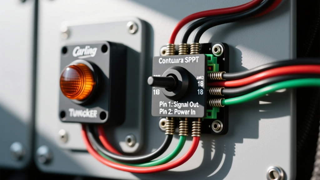
The Shift from Steering Stalks to Custom Rocker Panels
In custom hot rods, off-road buggies, and marine applications, the traditional steering column turn signal stalk is often the first component to be eliminated. Fabricators favor clean, minimalist dash panels, which necessitates the use of a turn signal rocker switch. However, selecting the correct switch topology is not as simple as picking a standard ON/OFF SPST rocker for fog lights. Turn signals require specific circuit logic, flasher relay integration, and in many cases, auto-canceling capabilities to remain street-legal and functional.
This guide compares the two primary rocker switch configurations used for custom turn signals: Maintained (Latching) SPDT and Momentary ON-OFF-ON. We will cover pinout configurations, AWG wire sizing, flasher relay compatibility, and the integration of smart modules to replicate OEM auto-canceling behavior.
Switch Topology Comparison: Latching vs. Momentary
The most common waterproof rocker switches on the market, such as the Carling V-Series Contura II and V, are available in multiple internal circuit configurations. Choosing the right one dictates how your flasher relay and dash indicators will behave.
1. Latching SPDT (ON-OFF-ON) - The Maintained Approach
A latching Single Pole Double Throw (SPDT) switch stays in the LEFT or RIGHT position until the driver manually pulls it back to the CENTER (OFF) position.
- Pros: Simple wiring; directly interfaces with standard 3-pin thermal or electronic flasher relays; no external smart modules required for basic flashing.
- Cons: Lacks auto-canceling. The driver must remember to manually switch off the signal after a turn, which is a safety hazard and illegal for street use in most jurisdictions.
- Best Application: Off-road hazard lights, marine navigation indicators, or trailer auxiliary lighting where auto-canceling is irrelevant.
2. Momentary ON-OFF-ON - The OEM Replica Approach
A momentary switch springs back to the center OFF position the moment the driver releases it. Because the switch does not maintain the circuit, it cannot power a standard flasher relay directly. Instead, it acts as a low-amperage trigger for a Smart Turn Signal Module.
- Pros: Mimics the feel of an OEM stalk; enables the use of auto-canceling modules (via steering wheel angle sensors, GPS, or timed relays).
- Cons: Requires a more complex wiring harness and an external control module (e.g., Dakota Digital SGI-5 or Painless Performance programmable modules).
- Best Application: Street-legal custom builds, high-end restomods, and motorcycles where manual canceling is impractical.
Technical Pinout and Wiring Matrix
Understanding the terminal layout is critical before crimping your harness. Below is the standard pinout reference for a 6-pin Carling-style SPDT rocker switch (ON-OFF-ON) and a 10-pin DPDT momentary switch used in advanced LED setups.
| Switch Type | Pin Number | Function / Connection | Recommended AWG | SAE Wire Color Code |
|---|---|---|---|---|
| Latching SPDT (6-Pin) | Pin 1 | Left Turn Load (To Flasher/Bulbs) | 14 AWG | Yellow |
| Pin 2 | 12V Fused Source (Ignition) | 14 AWG | Red | |
| Pin 3 | Right Turn Load (To Flasher/Bulbs) | 14 AWG | Dark Green | |
| Momentary DPDT (10-Pin) | Pin 2 & 5 | Ground / Signal Trigger Inputs | 16 AWG | Black |
| Pin 3 & 6 | Trigger Outputs to Smart Module | 16 AWG | Light Blue | |
| Pin 7 | Rocker LED Illumination (+) | 18 AWG | Orange (Dimmer) | |
| Pin 8 | Rocker LED Illumination (-) | 18 AWG | Black |
Integrating Flasher Relays and LED Loads
The most common failure point in custom turn signal wiring is a mismatch between the flasher relay type and the bulb load. According to SAE J1122 vehicular switch standards, circuits must be rated for the specific thermal and electrical loads they carry.
Thermal vs. Solid-State Flashers
If you are using a latching SPDT rocker with traditional 1157 incandescent bulbs, a standard thermal flasher relay (like the Tridon 552) will work perfectly. Thermal flashers rely on the heat generated by the current draw (typically 4.2A to 8A) to bend a bimetallic strip and break the circuit, creating the 'click' and the flash.
However, if your custom build utilizes LED tail lights and marker lights, the current draw drops to less than 0.5A. A thermal flasher will not generate enough heat to cycle, resulting in a solid light or a hyper-flash. You must upgrade to an Electronic Solid-State Flasher (e.g., Novita EP35 or Tridon EL14). These rely on an internal IC timer rather than thermal expansion and will flash at a consistent 80-120 cycles per minute regardless of the load.
Handling Rocker Switch Backfeed with LEDs
When wiring illuminated turn signal rocker switches, the internal indicator LEDs can cause 'backfeed' or 'ghosting'. If the switch's internal LED shares a common ground with the dash illumination circuit, voltage can leak backward through the flasher relay, causing the opposite turn signal to dimly glow or the flasher to click erratically. The Fix: Use an SPDT switch with an independent LED ground pin (Pin 8 on a Contura V), and wire it directly to a clean chassis ground, completely isolating it from the dash dimmer ground bus.
Wire Gauge, Routing, and Weatherproofing
Custom dash panels often require running harnesses through tight firewall grommets and behind aluminum dash inserts. Follow these specifications to prevent voltage drop and fire hazards:
- Wire Type: Use SAE J1128 TXL (Thin-wall cross-linked) or GXL primary wire. TXL has a smaller outer diameter than standard PVC wire, allowing you to bundle more circuits into a single Deutsch connector or firewall pass-through.
- Main Feed (Pin 2): 14 AWG is mandatory. Even if your LEDs only draw 2A, the switch must be rated for the fuse protecting the circuit (typically 10A or 15A). Using 16 AWG on a 15A fuse risks melting the switch housing in the event of a dead short before the fuse blows.
- Connectors: Do not use standard vinyl quick-disconnects behind the dash where they can vibrate loose. Use Deutsch DT series 4-cavity plugs for the main harness connection, and heat-shrink solder sleeves for any splices. For the switch terminals, use nylon-insulated female spade connectors with a wire grip crimp.
- Weatherproofing: For door-mounted rockers or open-cabin buggies, ensure you are using Contura V-Series actuators, which feature an IP68 sealing rating via a silicone o-ring and double-barrier internal seals.
Troubleshooting Common Rocker Switch Failures
When a custom turn signal circuit fails, the issue is rarely the switch itself, but rather the peripheral wiring. Use this diagnostic tree:
- Symptom: Switch feels stiff or clicks erratically.
Cause: Debris inside the switch housing or using a switch rated below the circuit amperage, causing internal arcing and pitting on the copper contacts.
Fix: Replace with an IP68 sealed Carling V-Series switch and verify the inline fuse is no larger than 15A. - Symptom: Hyper-flashing with solid-state relay.
Cause: The smart module or solid-state flasher requires a minimum load to trigger the timing circuit, or the ground wire on a 3-pin LED flasher is not secured.
Fix: Verify the 3-pin flasher ground is tied to bare metal. If using a 2-pin flasher, install 50W 6-Ohm load resistors in parallel with the LED bulbs. - Symptom: Left turn signal activates the right dash indicator.
Cause: Backfeed through the dash indicator bulb or shared LED grounds.
Fix: Install 1N4001 blocking diodes on the trigger wires between the rocker switch and the smart module or flasher relay to enforce one-way current flow.
Conclusion: Matching the Switch to the Build
For off-road and marine applications where simplicity and waterproofing are paramount, the latching SPDT Contura rocker paired with an electronic solid-state flasher is the undisputed choice. However, for street-driven customs, hot rods, and motorcycles, investing in a momentary ON-OFF-ON switch wired to a programmable smart module like the Painless Performance Turn Signal Module provides the OEM-level auto-canceling and safety features required for modern driving. Always prioritize TXL wiring, proper AWG sizing, and isolated LED grounds to ensure a flawless, fire-safe installation.