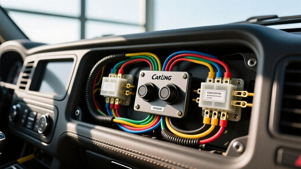
Project Overview: Upgrading to a Sealed Rocker Switch Panel
When managing multiple high-draw off-road accessories—such as LED light bars, air compressors, and winch solenoids—relying on cheap, unsealed toggle switches is a recipe for electrical failure. Moisture intrusion, UV degradation, and internal arcing frequently lead to melted housings and voltage drops. Upgrading to a centralized, IP68-sealed rocker switch panel, specifically utilizing the industry-standard Carling Contura V-Series, provides a watertight, dustproof, and highly reliable command center for your vehicle's auxiliary systems.
This upgrade and modification guide details the complete electrical architecture required to install a 6-gang rocker switch panel. We will cover main power distribution, voltage drop mitigation, ISO mini relay integration, and the precise 7-pin configuration required to independently control the switch's upper and lower LED illumination circuits. By adhering to SAE J1128 Low Tension Primary Cable standards and proper termination protocols, you will build a harness capable of surviving harsh environmental conditions while delivering clean, stable voltage to your accessories.
Required Components and AWG Specifications
Before beginning the fabrication of your custom wiring harness, gather the following automotive-grade components. Do not use residential THHN wire or cheap copper-clad aluminum (CCA) wire; always specify stranded, oxygen-free copper (OFC) wire with cross-linked polyethylene (XLPE) or PVC insulation rated for 105°C.
| Component | Specification / Rating | Application |
|---|---|---|
| Primary Wire (Main Feed) | 8 AWG Stranded OFC (Red/Black) | Battery to centralized fuse block |
| Primary Wire (Switch Feed) | 12 AWG Stranded OFC (Red) | Fuse block to rocker switch Pin 8 & 7 |
| Primary Wire (Load/Relay) | 12 AWG Stranded OFC (Blue/Yellow) | Switch Pin 3 to Relay Pin 86 |
| Relays | Bosch-Style ISO Mini 5-Pin (40A) | Switching high-draw accessories |
| Flyback Diodes | 1N4001 Rectifier Diode | Across relay pins 85/86 for spike suppression |
| Terminals | Adhesive-Lined Heat Shrink (3:1 Ratio) | All crimp connections for moisture sealing |
Step 1: Main Power Distribution and Voltage Drop Mitigation
A common failure point in custom rocker switch panel installations is undersizing the main power feed wire. A 6-gang panel controlling multiple 40A relays can theoretically draw significant current if multiple accessories are engaged simultaneously. To mitigate voltage drop, you must calculate the required AWG based on the total length of the wire run and the maximum anticipated amperage.
Using the standard voltage drop formula: VD = (2 × L × I × R) / 1000 (where L is one-way length in feet, I is current in amps, and R is wire resistance per 1000 ft), we can determine the correct gauge. For a 15-foot run from the battery to the cabin-mounted panel carrying a potential 30A continuous load, 10 AWG wire yields a voltage drop of roughly 0.45V. While acceptable, upgrading to 8 AWG primary wire reduces this drop to 0.28V, ensuring your relays receive a solid 12.5V+ trigger signal, which prevents relay chatter and premature contact pitting.
Route the 8 AWG main feed from the battery's positive terminal through a high-amp ANL or Mega fuse (rated 25% higher than your max continuous draw) into a centralized, sealed fuse block (such as a Blue Sea Systems ST Blade). This block will distribute fused 12 AWG feeds to the individual switches on your panel.
Step 2: Bosch-Style Relay Integration for High-Draw Loads
While Carling Contura switches are rated for 20A at 12V DC, it is an industry best practice to use the switch solely as a low-current trigger for a mechanical relay when handling inductive loads (winches, compressors) or lighting arrays exceeding 10A. This prevents the internal copper wiper of the switch from arcing and degrading over time.
For each accessory, wire a standard 5-pin ISO mini relay using the following configuration:
- Pin 30: 12 AWG Red wire from the battery (fused at the source via an ATC blade fuse).
- Pin 87: 12 AWG wire to the accessory's positive input.
- Pin 86: 12 AWG Blue wire from the rocker switch output (Pin 3).
- Pin 85: 12 AWG Black wire to a dedicated, clean chassis ground.
Expert Tip - Flyback Diode Integration: When you deactivate a rocker switch controlling an inductive load, the collapsing magnetic field in the relay coil generates a high-voltage reverse spike. Over time, this spike will pit the contacts inside your rocker switch panel. Solder a 1N4001 diode across the relay's Pin 85 and Pin 86, with the diode's cathode (silver stripe) facing Pin 86. This creates a recirculation path for the voltage spike, extending the lifespan of your switch contacts exponentially. For more on protecting automotive circuits, refer to Painless Performance Products Wiring Manuals.
Step 3: Carling Contura V-Series 7-Pin Configuration
The Carling Contura V-Series is the gold standard for off-road rocker switch panels due to its IP68 sealing and modular actuator caps. A standard Single Pole, Single Throw (SPST) switch with dual independent LEDs utilizes 5 of the 7 available pins. Understanding this pinout matrix is critical for achieving proper daytime and nighttime illumination without causing parasitic battery drain.
Rocker Switch Pinout Matrix
| Pin Number | Function | Wire Color | Connection Destination |
|---|---|---|---|
| Pin 8 | Main 12V+ Input | Red | Ignition-switched 12V source (Fuse Block) |
| Pin 3 | Switched Output | Blue | Relay Pin 86 (Trigger) |
| Pin 2 | Upper LED Ground | Black | Chassis Ground (Controls Daytime LED) |
| Pin 7 | Lower LED 12V+ Input | White/Green | Headlight/Parking Light Circuit (Dash Illumination) |
| Pin 6 | Lower LED Ground | Black | Chassis Ground (Controls Nighttime LED) |
Illumination Logic: By wiring Pin 8 to an ignition-switched fuse, the upper LED (and the accessory) will only have power when the vehicle is running, preventing you from accidentally leaving a light bar on and draining the battery. The upper LED illuminates whenever Pin 8 receives 12V and Pin 2 is grounded. The lower LED is tied to Pin 7; by connecting Pin 7 to your vehicle's headlight or parking light circuit, the lower LED acts as a dash dimmer indicator, illuminating only when your headlights are turned on for night driving.
Step 4: Termination, Crimping, and Weatherproofing
The environment underneath a dashboard or inside a center console is subject to extreme temperature fluctuations and condensation. Soldering alone is prohibited in high-vibration automotive environments because solder wicks into the wire strands, creating a rigid point that will eventually fatigue and snap. Instead, utilize high-quality open-barrel or closed-barrel crimp terminals.
After crimping, seal every connection using adhesive-lined polyolefin heat shrink tubing with a 3:1 shrink ratio. When heated, the inner layer of thermoplastic adhesive melts and flows into the wire strands, creating a completely watertight, oxygen-free seal that prevents galvanic corrosion. For connections that plug directly into relays or accessories, use sealed connector systems like Delphi Weather-Pack or Deutsch DT series, applying a small amount of dielectric grease to the pins prior to mating to prevent moisture ingress and fretting corrosion.
Troubleshooting Common Installation Failures
Even with meticulous planning, custom wiring projects can present issues during the initial power-up. Use this diagnostic tree to resolve common rocker switch panel anomalies:
- Symptom: Upper LED illuminates, but accessory does not turn on.
Cause: Faulty relay trigger circuit or blown accessory fuse.
Fix: Use a multimeter to check for 12V at Relay Pin 86 when the switch is engaged. If 12V is present, check Relay Pin 30 for constant battery voltage and verify the ground at Pin 85. - Symptom: Accessory turns on, but upper LED does not illuminate.
Cause: Open circuit on Pin 2 (Upper LED Ground).
Fix: Verify continuity between Pin 2 and the chassis ground. Ensure the ring terminal is secured to bare, unpainted metal. - Symptom: Lower LED remains illuminated even when headlights are off.
Cause: Pin 7 is wired to a constant 12V source instead of the headlight dimmer/parking light circuit.
Fix: Trace the wire on Pin 7 and relocate it to a verified parking light circuit using a multimeter or logic probe. - Symptom: Switch housing feels warm to the touch after extended use.
Cause: The switch is carrying the full load of the accessory instead of just triggering a relay, or the wire gauge is undersized causing resistance.
Fix: Immediately disconnect power. Rewire the system to incorporate a mechanical relay, ensuring the switch only handles the <1A relay coil trigger current.
For comprehensive datasheets regarding switch actuator torque, IP68 testing parameters, and dimensional CAD files, always consult the Carling Technologies Contura V-Series Datasheet. Proper planning, adherence to AWG sizing, and meticulous termination will ensure your custom rocker switch panel operates flawlessly for the lifetime of the vehicle.