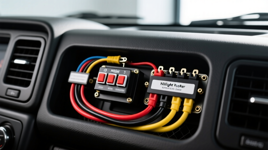
Mastering the Nilight 3 Pin Rocker Switch Install
Upgrading your off-road vehicle with auxiliary lighting, air compressors, or winch controllers requires a reliable interface inside the cabin. The Nilight 3-pin rocker switch is an industry favorite due to its SPST (Single Pole, Single Throw) design, integrated LED illumination, and standard 1.45-inch by 0.83-inch cutout dimensions. However, a proper Nilight 3 pin rocker switch install goes far beyond simply plugging in wires. Incorrect pin mapping can instantly fry the internal LED resistor, while undersized wiring can lead to voltage drop, melted housings, or even electrical fires.
This comprehensive guide details the exact pinout configuration, American Wire Gauge (AWG) requirements, and Bosch-style relay integration necessary to execute a professional-grade, marine-level installation that adheres to SAE J1128 low-tension cable standards for automotive environments.
Understanding the 3-Pin SPST Architecture
Before cutting a single wire, you must understand the internal topology of the switch. A 3-pin rocker switch is an SPST switch with a built-in indicator light. The internal LED requires a dedicated ground path to illuminate when the circuit is closed. If you apply 12V power to the ground pin, the LED will pop, and the switch will be permanently ruined.
| Pin Position | Internal Function | Recommended Wire Color | Connection Destination |
|---|---|---|---|
| Pin 1 (Top) | Power Source (In) | Red (18 AWG) | Fused 12V Ignition Source |
| Pin 2 (Middle) | Load / Accessory (Out) | Blue (18 AWG) | Relay Trigger (Pin 86) |
| Pin 3 (Bottom) | Internal LED Ground | Black (18 AWG) | Chassis Ground or Relay Pin 85 |
Note: Always verify pin numbers with a multimeter set to continuity mode before applying power. Manufacturing runs can occasionally swap Pin 1 and Pin 2 orientations depending on the specific Nilight batch.
Pre-Installation: Sizing Your Circuit and Components
The most common failure in aftermarket off-road wiring is routing high-amperage loads directly through the rocker switch. While the Nilight switch is technically rated for 20 Amps at 12V DC, running a 20A continuous load (like a 50-inch LED light bar) through the switch contacts will generate excessive heat, causing voltage drop and eventually melting the ABS plastic housing. Always use a relay for loads exceeding 10 Amps.
| Accessory Draw | Primary Wire Gauge (AWG) | Max Inline Fuse | Typical Application |
|---|---|---|---|
| 0 - 5 Amps | 16 AWG | 5A - 7.5A | Interior LEDs, small solenoids |
| 5 - 15 Amps | 14 AWG | 15A | Small light bars, air horns |
| 15 - 30 Amps | 10 AWG | 30A | 50-inch LED Light Bars |
| 30 - 50 Amps | 8 AWG | 50A | Heavy winches, dual compressors |
For the switch circuit itself (the wires connecting to Pins 1, 2, and 3), 18 AWG stranded copper wire is perfect. The switch only needs to carry the trigger current for the relay coil, which typically draws less than 150 milliamps (0.15A).
Step-by-Step Nilight 3 Pin Rocker Switch Install
Step 1: Prep the Dash and Switch Housing
Use a specialized rocker switch cutout tool or a Dremel with a plastic-cutting bit to create a 1.45' x 0.83' rectangular hole in your dash or overhead console. Deburr the edges with a file to prevent the plastic switch housing from snagging or cracking during insertion. Wrap the edges of the cutout with 3M UHMW polyethylene tape to prevent squeaks and galvanic corrosion between the switch and metal dash panels.
Step 2: Route the Switch Wires (The Trigger Circuit)
Cut three lengths of 18 AWG wire (Red, Blue, Black). Crimp 0.250-inch (1/4') female fully-insulated quick disconnect terminals onto one end of each wire. Use a ratcheting crimper to ensure a gas-tight connection; a loose crimp will cause arcing inside the switch cavity. Slide 3:1 adhesive-lined marine heat shrink over the crimps and apply heat until the adhesive seals the wire insulation.
Step 3: Tap into an Ignition-Switched Power Source
Locate a fuse in your interior fuse box that is only active when the key is in the 'ON' or 'ACC' position (e.g., the cigarette lighter or rear wiper circuit). Use an Add-A-Circuit (fuse tap) to pull 12V power. Connect the Red wire (Pin 1) to this fused tap. Crucial: Install a 3A inline ATC fuse on this red wire within 6 inches of the power source to protect the 18 AWG trigger wire.
Step 4: Establish the Ground Path
Connect the Black wire (Pin 3) to a clean, bare-metal chassis ground. Use a #8 ring terminal, sand away any paint or powder coating at the grounding point, and secure it with a stainless steel bolt and star washer. Apply dielectric grease over the terminal after tightening to 15 lb-ft of torque to prevent moisture intrusion.
Step 5: Connect to the Relay Trigger
Run the Blue wire (Pin 2) through the firewall using an existing rubber grommet. Connect this wire to Pin 86 on your standard Bosch-style ISO mini relay. This completes the switch circuit. When you flip the Nilight switch, 12V flows from Pin 1 to Pin 2, energizing the relay coil and lighting up the switch's internal LED via Pin 3's ground path.
Integrating the Bosch-Style Relay (The Heavy Lifting)
To power the actual accessory (e.g., a 20A LED light bar), you must wire the high-current side of the relay. According to Littelfuse automotive relay specifications, standard ISO mini relays are rated for 30A to 40A continuous duty.
- Pin 30 (Common): Connect to the vehicle battery's positive terminal via a heavy-gauge wire (e.g., 10 AWG) with a 30A inline MAXI fuse located within 18 inches of the battery.
- Pin 87 (Normally Open): Connect to the positive input wire of your LED light bar or accessory.
- Pin 85 (Coil Ground): Connect to a solid chassis ground. (You can also wire Pin 85 and the switch's Pin 3 to the same ground point to save wire).
- Pin 86 (Coil Power): This is where your Blue wire from the Nilight switch (Pin 2) connects.
Mount the relay in a protected, dry area under the hood or behind the dash. Use a relay harness socket with molded pigtails rather than splicing directly onto the relay spades, which invites moisture and vibration failures.
Troubleshooting Real-World Failure Modes
Even with meticulous planning, electrical gremlins can appear. Here is a diagnostic decision tree for common issues encountered after a Nilight 3 pin rocker switch install:
Symptom: The Switch LED Stays On Even When Switched Off
Cause: You have wired Pin 1 and Pin 2 backward, or you are using a relay with a built-in flyback diode/suppressor wired in reverse polarity. If the relay's internal diode allows current to bleed backward through the coil when the switch is off, it will provide enough milliamps to faintly illuminate the Nilight LED.
Fix: Swap the wires on Pin 1 and Pin 2. If the issue persists, install a 1N4001 rectifier diode inline on the Blue trigger wire, with the stripe facing toward the relay, to block reverse current bleed.
Symptom: The Switch Melts or Feels Hot to the Touch
Cause: You bypassed the relay and routed the full amperage of the accessory (e.g., 15A+) directly through the switch contacts. The internal copper contacts are undersized for continuous high-amp loads, leading to high resistance and thermal runaway.
Fix: Immediately disconnect the battery. Rewire the circuit to include a Bosch-style relay so the switch only handles the 0.15A relay coil trigger current.
Symptom: Accessory Turns On, But Switch LED Does Not Illuminate
Cause: Pin 3 (Ground) is not making a solid connection, or the internal LED resistor has blown due to a voltage spike (common when jump-starting a vehicle with the switch on).
Fix: Test the Black ground wire with a multimeter for continuity to the battery negative terminal. If the ground is solid, the internal LED is dead. The switch will still function as a mechanical SPST toggle, but it will need replacement if illumination is required.
Final Expert Advice for Longevity
To ensure your installation survives harsh off-road environments, treat all exposed copper and crimp connections with an adhesive-lined, dual-wall heat shrink tubing. Standard PVC electrical tape will unravel under hood temperatures exceeding 140°F (60°C). Furthermore, always route your wiring away from exhaust headers and sharp chassis edges, securing the loom with UV-resistant nylon zip ties every 12 inches. By adhering to these standards and utilizing proper relay isolation, your Nilight switch setup will provide years of reliable, spark-free operation. For further reading on automotive wire insulation temperature ratings, refer to the Nilight Official Specifications and SAE documentation.