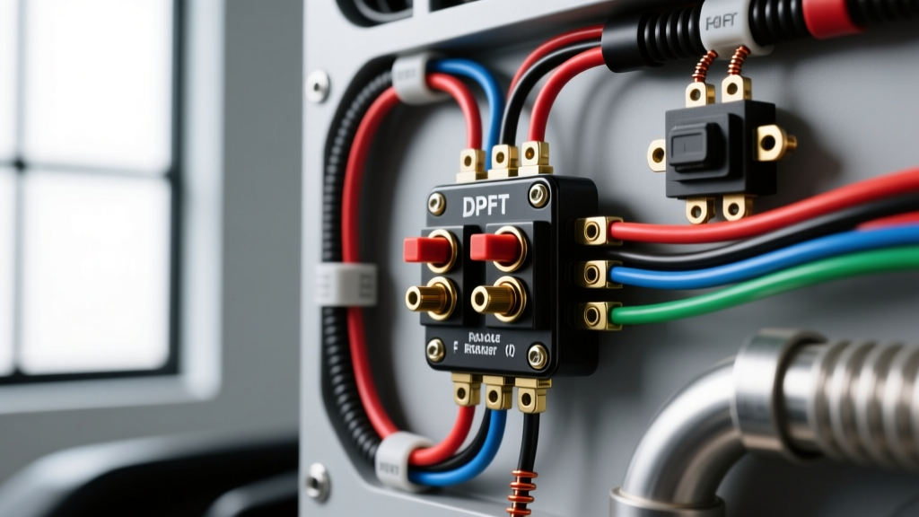
Understanding the Double Pole Double Throw Rocker Switch
When building custom automotive electrical systems, controlling reversible 12V DC motors—such as winches, power windows, aftermarket seat sliders, or motorized antenna masts—requires a specific type of switch. The double pole double throw rocker switch (commonly abbreviated as DPDT) is the fundamental component for these applications. Unlike a standard single-pole switch that simply interrupts power, a DPDT switch manages two separate circuits simultaneously and routes current in multiple directions.
To break down the terminology: 'Double Pole' means the switch has two completely isolated internal circuits (or 'poles'). 'Double Throw' means each pole can connect to one of two different output paths. In automotive applications, we typically use an ON-ON or ON-OFF-ON DPDT configuration. This allows the switch to route positive and negative voltage to a motor's terminals in one position, and physically swap that polarity in the opposite position, effectively reversing the motor's direction without the need for complex electronic controllers.
The 6-Pin Anatomy and Polarity Reversal Logic
A standard automotive DPDT rocker switch features six spade terminals on its rear housing. Understanding how these pins interact internally is the most critical step for beginners. If wired incorrectly, a DPDT switch can create a dead short across your vehicle's battery, potentially melting wire harnesses or causing an electrical fire.
Internally, the switch is divided into two rows. The center pins (Pins 2 and 5) are the common inputs. The outer pins (1, 3, 4, and 6) are the switched outputs. When you toggle the switch 'UP', Pin 2 connects to Pin 1, and Pin 5 connects to Pin 4. When you toggle it 'DOWN', Pin 2 connects to Pin 3, and Pin 5 connects to Pin 6.
Standard DPDT Pinout Reference
| Position | Left Column | Center Column (Input) | Right Column |
|---|---|---|---|
| Top Row | Pin 1 (Output A1) | Pin 2 (Input 1) | Pin 3 (Output A2) |
| Bottom Row | Pin 4 (Output B1) | Pin 5 (Input 2) | Pin 6 (Output B2) |
Step-by-Step: Wiring the 'X' Crossover Circuit
To achieve polarity reversal for a DC motor, we use a wiring technique known as the 'X' crossover. This setup uses jumper wires on the back of the switch to swap the positive and negative feeds depending on the toggle position. Follow these steps precisely using 16 AWG or 14 AWG primary wire for the switch jumpers, and appropriate gauge wire for the motor feed.
- Prepare the Power Inputs: Run a 12V+ fused feed from your battery or fuse block to Pin 2. Run a dedicated chassis ground wire to Pin 5.
- Install the Input Jumper: Crimp a short jumper wire connecting Pin 2 to Pin 5. This ensures both internal poles receive power and ground simultaneously.
- Install the 'X' Output Jumpers: Crimp a jumper wire from Pin 1 to Pin 6. Then, crimp a second jumper wire from Pin 3 to Pin 4. These crossed jumpers are the secret to reversing the polarity.
- Connect the Motor: Run Motor Wire A to Pin 1. Run Motor Wire B to Pin 3. (Alternatively, you can use Pins 4 and 6; the logic remains identical).
- Verify the Logic: In the UP position, Pin 1 receives 12V+ and Pin 3 receives Ground. In the DOWN position, Pin 3 receives 12V+ and Pin 1 receives Ground. The motor spins in the opposite direction.
Wire Sizing and Environmental Standards
Automotive environments are harsh. Vibrations, moisture, and extreme temperature fluctuations demand adherence to strict engineering standards. When selecting wire for your DPDT switch harness, always reference SAE J1128 specifications for low-tension battery and primary cable insulation. For switches mounted externally or in the engine bay, ensure the switch body carries an IP68 ingress protection rating and complies with SAE J1455 environmental testing standards for heavy-duty commercial vehicles.
AWG Sizing Chart for 12V DC Switch Circuits
| Max Continuous Draw | Recommended Wire Gauge (AWG) | Typical Application | Terminal Type |
|---|---|---|---|
| Up to 6 Amps | 18 AWG | LED Illumination, Low-draw solenoids | 250 Series Spade |
| Up to 10 Amps | 16 AWG | Switch jumpers, small linear actuators | 250 Series Spade |
| Up to 15 Amps | 14 AWG | Power windows, seat motors, sunroofs | 250 Series Spade |
| Up to 20 Amps | 12 AWG | High-torque wiper motors, small winches | Heavy Duty Spade / Ring |
Note: Always use marine-grade adhesive-lined heat shrink spade terminals to prevent moisture wicking into the copper strands, which causes green corrosion and high-resistance voltage drops.
High-Draw Applications: Integrating Relays and Solenoids
A common beginner mistake is attempting to wire a high-amperage device, like a 3,000 lb ATV winch or a heavy-duty hydraulic pump, directly through the spade terminals of a standard 20A DPDT rocker switch. Winches can pull 100 to 300 amps under load. Pushing this current through a dashboard switch will instantly melt the plastic housing and weld the internal copper contacts together.
For high-draw motors, the DPDT switch must only be used as a low-current trigger. You will wire the switch's output pins (1, 3, 4, and 6) to the coils of heavy-duty automotive relays or a dedicated winch solenoid contactor. According to Carling Technologies engineering datasheets, utilizing the switch to trigger a relay coil limits the current passing through the rocker to less than 2 amps, ensuring a lifetime of reliable operation. Furthermore, when controlling inductive loads like DC motors, it is highly recommended to install a flyback diode across the motor terminals or relay coils to suppress inductive kickback voltage spikes that can damage sensitive vehicle ECUs.
Troubleshooting Common DPDT Installation Errors
Even with a clear wiring diagram, custom installations can present challenges. Use this decision tree to diagnose common DPDT switch failures:
- Symptom: The motor only spins in one direction.
Cause: One of the 'X' crossover jumpers is loose, or the ground feed to Pin 5 is missing. Use a multimeter to verify continuity between Pin 5 and chassis ground, and check the crimp on the Pin 3-to-4 jumper. - Symptom: The switch feels 'mushy' or the fuse blows immediately.
Cause: A dead short. You likely wired the power input to an output pin, or the jumper wires are touching bare metal. Disconnect the battery, isolate the spade terminals with heat shrink boots, and verify pin assignments. - Symptom: The switch housing is hot to the touch.
Cause: Overcurrent or high resistance. The motor is drawing more amperage than the switch's rated capacity, or the spade terminals were crimped poorly, creating a high-resistance bottleneck. Upgrade to a relay-triggered circuit immediately.
Authoritative References
For further reading on automotive electrical standards and switch specifications, consult the following resources:
- SAE J1128: Low Tension Battery and Primary Cable - Society of Automotive Engineers.
- SAE J1455: Recommended Environmental Practices for Electronic Equipment Design - Society of Automotive Engineers.
- Carling Technologies V-Series Rocker Switch Datasheets - Engineering specifications for DPDT pinouts and IP68 sealing.