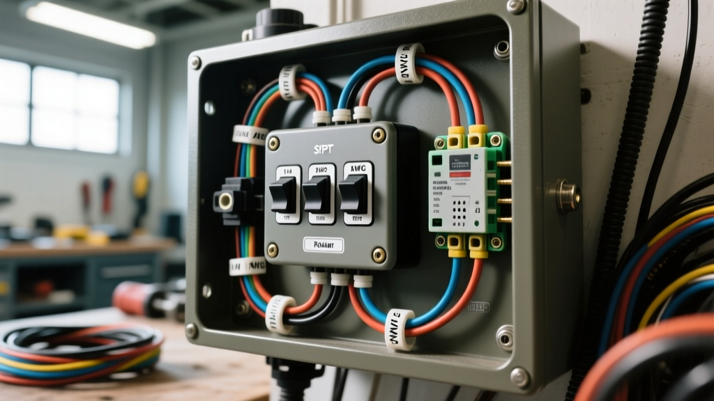
Why Choose a Marine Rocker Switch Panel for Off-Road and Automotive Use?
When outfitting an overland vehicle, off-road rig, or boat with auxiliary lighting, winches, or air compressors, a standard automotive toggle switch simply will not survive the elements. A marine rocker switch panel is engineered to withstand harsh environments, featuring IP65 or IP68 waterproof ratings, UV-resistant faceplates, and internal contacts designed to resist salt spray and moisture intrusion. For beginners stepping into custom 12V DC wiring, these panels offer a modular, standardized approach to circuit control. However, treating a marine switch exactly like a standard automotive switch is a common pitfall that leads to melted terminals and voltage drop. This guide breaks down the beginner-friendly fundamentals of wiring a 3-pin SPST (Single Pole, Single Throw) marine rocker switch panel, incorporating American Boat and Yacht Council (ABYC) best practices that translate perfectly to rugged automotive applications.
Understanding the Standard 3-Pin SPST Pinout
The most common switch found in a marine rocker switch panel is the 3-pin SPST with an integrated LED indicator. Unlike a simple 2-pin automotive switch that merely breaks the hot wire, the 3-pin marine switch requires a dedicated ground to illuminate the internal LED when the circuit is closed. Miswiring these pins is the number one cause of blown fuses and fried switch LEDs among beginners.
Standard 3-Pin Marine Rocker Switch Pin Configuration
| Pin Number | Function | Wire Color (Standard) | Connection Destination |
|---|---|---|---|
| Pin 1 | LED Ground | Black | Common Ground Bus Bar / Chassis |
| Pin 2 | Load / Output | Blue or White | Accessory Positive (or Relay Pin 86) |
| Pin 3 | 12V DC Source | Red | Fused 12V+ Battery Source |
Note: Pin 3 is typically located in the center or marked with a '+' symbol on the switch housing. Always verify with a multimeter before applying power.
Wire Gauge Selection: ABYC vs. SAE Standards
In automotive wiring, SAE J1128 standards are common, but for marine and severe off-road environments, the ABYC E-11 standards recommend using tinned, stranded copper wire. Tinned copper resists galvanic corrosion and the 'black wire' syndrome (copper oxidation) that causes high resistance and voltage drop. When sizing your wire, you must calculate based on the total round-trip length of the circuit (positive + negative) and the maximum amperage draw of the accessory.
12V DC AWG Sizing Chart for Marine/Off-Road Accessories
| Wire Gauge (AWG) | Max Ampacity (ABYC) | Recommended Fuse Size | Ideal Use Case |
|---|---|---|---|
| 18 AWG | 10 Amps | 5A - 7.5A | Switch LED grounds, low-draw relays |
| 16 AWG | 13 Amps | 10A | Interior LEDs, small gauges, horn |
| 14 AWG | 18 Amps | 15A | Standard LED light bars, water pumps |
| 12 AWG | 25 Amps | 20A | Large light bars, 12V fridges, air horns |
| 10 AWG | 35 Amps | 30A | Winch solenoid triggers, heavy inverters |
For a deeper dive into circuit protection and wire sizing, the Blue Sea Systems Circuit Protection Chart is an industry-standard reference that aligns with both ABYC and SAE J1128 guidelines.
When to Use a Relay: Protecting Your Switch
A common beginner mistake is running a high-draw accessory, like a 30-amp LED light bar or an air compressor, directly through the marine rocker switch. Most standard marine switches are rated for 20 amps at 12V DC. Running 25+ amps through the switch's internal contacts will generate excessive heat, melting the plastic housing and creating a fire hazard. For any accessory drawing more than 15 amps, you must use the rocker switch merely as a low-amp trigger for a standard 4-pin automotive relay.
4-Pin Relay Wiring for High-Draw Accessories
| Relay Pin | Function | Connection Source / Destination | Wire Gauge |
|---|---|---|---|
| 86 | Trigger (+) | From Rocker Switch Pin 2 (Load) | 18 AWG |
| 85 | Trigger (-) | Common Ground Bus Bar | 18 AWG |
| 30 | High Amp Source (+) | Direct from Battery (via 30A+ Fuse) | 10 or 8 AWG |
| 87 | High Amp Output (+) | To Accessory Positive Terminal | 10 or 8 AWG |
Step-by-Step Installation Guide for Beginners
Step 1: Planning the Circuit and Fusing
The golden rule of 12V wiring is that the fuse protects the wire, not the accessory. If you are using 14 AWG wire (rated for 18 amps), your fuse must be 15 amps or lower, regardless of what the accessory manual recommends. Install an ATC/ATO blade fuse holder or a marine-rated MRBF (Marine Rated Battery Fuse) terminal block within 7 inches of the positive battery terminal. This ensures that if the main feed wire chafes against the chassis, the fuse blows before a fire starts.
Step 2: Crimping and Adhesive Heat Shrink
Never use solder alone for marine or off-road wiring; the rigid solder joint will crack under vehicle vibration, leading to intermittent faults. Instead, use a ratcheting crimp tool to secure nickel-plated or tinned copper ring and butt terminals. After crimping, seal the connection using dual-wall adhesive-lined marine heat shrink. When heated, the inner wall melts and flows into the wire strands, creating a 100% waterproof, airtight seal that prevents capillary action from wicking moisture into the copper.
Step 3: Routing and Split Loom Protection
Route your wiring harness away from exhaust components, steering shafts, and sharp metal edges. Bundle the wires using split wire loom tubing and secure them with UV-resistant nylon cable ties every 12 to 18 inches. Where the harness passes through the firewall or a metal bulkhead, always use a rubber grommet and apply a dab of silicone sealant to maintain the cabin's weather-tight integrity.
Step 4: Establishing a Common Ground Bus Bar
Avoid grounding individual accessories directly to random chassis bolts. In modern vehicles with galvanized steel or aluminum components, chassis grounds are notoriously unreliable and prone to galvanic corrosion. Instead, mount a dedicated, insulated copper ground bus bar near your marine rocker switch panel. Run a single, heavy-gauge wire (e.g., 6 AWG or 4 AWG) from the negative battery terminal to this bus bar, and terminate all your switch Pin 1 grounds and relay Pin 85 grounds to this centralized point. Apply dielectric grease to the bus bar studs to prevent corrosion.
Common Troubleshooting & Real-World Failure Modes
- Switch LED Dimming or Flickering: This is almost always caused by voltage drop on the ground circuit. Check the connection between Pin 1 and your ground bus bar. If the ground wire is undersized or corroded, the LED will not receive a full 12V potential difference.
- Switch Housing Melting or Hot to the Touch: You have exceeded the 20A continuous rating of the switch. Immediately disconnect the battery, inspect the terminals for arcing damage, and rewire the circuit using a 4-pin relay as outlined above.
- Accessory Runs When Switch is OFF: You have likely swapped Pin 2 (Load) and Pin 3 (Source). In this reversed configuration, the internal LED circuit remains energized by back-feed from the accessory. Swap the red and blue/white wires on the back of the switch.
- Blown Fuses Upon Startup: Check for a short to ground. A common culprit is the Pin 1 (LED Ground) wire accidentally touching the 12V+ Pin 3 terminal or the switch's metal mounting bracket if it is not properly insulated.
Conclusion
Wiring a marine rocker switch panel does not require an engineering degree, but it does demand respect for 12V DC electrical principles. By adhering to ABYC wiring standards, utilizing tinned copper wire with adhesive heat shrink, and knowing exactly when to implement a relay, you will build a custom accessory panel that is both highly functional and completely reliable in the harshest off-road and marine environments.