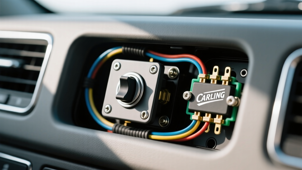
The Hidden Dangers of Poorly Executed Switch Panels
Upgrading a vehicle with custom accessory panels is a staple of off-road and overland builds. However, the installation of rocker switch plate covers—the bezels and faceplates that house Carling Contura or similar marine-grade switches—is frequently rushed. When installers focus solely on the aesthetic alignment of the plate cover while ignoring the electrical and mechanical realities behind it, the results range from annoying panel rattles to catastrophic thermal events and water-induced short circuits.
As an automotive electrical specialist, I see the aftermath of improper switch plate installations daily. Melted ABS plastics, corroded spade terminals, and parasitic draws caused by compromised IP67 seals are entirely preventable. This guide details the most common mistakes and critical safety warnings you must address when mounting rocker switch plate covers in custom dashboards, center consoles, and overhead panels.
Dimensional & Panel Prep Mistakes: The Cutout Catastrophe
The most frequent physical mistake occurs before a single wire is crimped: improper panel cutout dimensions. Most premium rocker switch plate covers are designed to accept standard Carling V-Series / Contura switches, which require precise rectangular cutouts.
The 1.45" x 0.83" Rule and Panel Thickness
The industry-standard cutout for a single Contura switch is exactly 1.450" x 0.830" (36.8mm x 21.1mm). A common mistake is using a Dremel or jigsaw freehand, resulting in an oversized hole. When the hole is even 0.050" too large, the switch’s polyurethane gasket cannot compress properly against the plate cover, destroying the waterproof seal.
Furthermore, installers often ignore panel thickness requirements. Switch retaining tangs are engineered to grip panels between 0.062" and 0.187" (1.5mm to 4.75mm). If you are mounting a switch plate cover on a thick fiberglass overhead console (common in Jeep Wrangler JK/JL or Toyota Tacoma builds) that exceeds 0.187", the switch will not snap into the bezel securely. Under the vibration profiles defined by SAE J1455 for heavy-duty vehicle environments, a loose switch will rattle, causing the internal silver-alloy contacts to bounce, arc, and eventually weld themselves together in the "ON" position.
Thermal Overload and Melting Hazards Behind the Bezel
Rocker switch plate covers are typically molded from ABS plastic, polycarbonate, or nylon. These materials have relatively low thermal deformation points. A severe safety warning applies to installers who attempt to run high-amperage loads directly through the switch without utilizing an automotive relay.
Bypassing Relays on High-Amp Circuits
A standard Contura switch is rated for 20A at 12V DC. However, this is a peak rating, not a continuous duty rating. If you wire a 15A LED light bar or a 20A onboard air compressor directly through the switch, the internal resistance of the switch contacts will generate significant heat. Because the switch body is enclosed tightly behind the plastic rocker switch plate cover, this heat has nowhere to dissipate. The result is a melted switch housing that fuses to the plate cover, creating a severe fire hazard.
The Fix: Always use a high-quality automotive relay (e.g., Bosch-style 4-pin or 5-pin, or sealed Deutsch solid-state relays) for any accessory drawing more than 10A continuously. The switch should only handle the low-amperage trigger circuit (typically less than 0.5A) to activate the relay coil.
Environmental Sealing and IP67 Failures
Many custom switch plate covers advertise "Marine Grade" or "Waterproof" status, but installers frequently compromise these ratings during assembly.
- Peeling the Foam Gasket: Some plate covers come with a pre-applied closed-cell foam gasket on the rear mating surface. Installers sometimes peel this off, mistakenly believing it is protective shipping film. This immediately drops the assembly's ingress protection from IP67 to effectively zero, allowing water to bypass the bezel and drain directly into the vehicle's lower dash wiring harness.
- Ignoring the Rear Boot: True IP67/IP68 sealing requires a protective silicone boot over the rear spade terminals. If your plate cover is mounted in an open-top vehicle (like a Jeep Wrangler) or a marine environment, exposed 0.250" quick-disconnect spades behind the plate will corrode within months due to high humidity and condensation, leading to high-resistance connections and voltage drops.
Wiring & Termination Errors Behind the Panel
The space behind a rocker switch plate cover is notoriously cramped, especially in multi-gang (3, 4, or 5-switch) configurations. This lack of working space leads to severe termination shortcuts.
The Pliers Crimp Sin
Using standard pliers to crimp 14 AWG or 12 AWG wire into 0.250" insulated spade terminals is a critical failure point. Pliers do not apply uniform pressure, resulting in a cold crimp. Over time, thermal cycling (expansion and contraction) causes the wire to back out of the terminal. When this happens behind a multi-gang switch plate, the loose 12V+ red wire can easily short against the grounded metal dash frame or the metal casing of an adjacent switch.
Expert Standard: You must use a ratcheting crimping tool calibrated for insulated terminals. For ultimate reliability in high-vibration off-road applications, abandon standard spade terminals entirely. Instead, use switches with pre-molded Deutsch DT pigtail connectors. This allows you to crimp Deutsch solid pins to your harness wires in a comfortable, well-lit environment, and simply plug the sealed connector into the back of the switch panel.
Reference Chart: Switch Circuit Load vs. Wire Gauge
When wiring the harness that feeds into your rocker switch plate cover, adhere to SAE J1128 low-tension primary cable standards and Blue Sea Systems circuit protection guidelines for proper AWG sizing based on the length of the wire run (assuming a standard 10-foot round trip).
| Accessory Type | Max Continuous Load | Wire Gauge (AWG) | Relay Required? | Terminal Type Behind Plate |
|---|---|---|---|---|
| Relay Trigger / LED Indicator | < 1.0A | 18 AWG | No | 0.110" Spade or Deutsch Pin |
| LED Light Bar (Small) | 5A - 10A | 14 AWG | Highly Recommended | 0.250" Insulated Spade |
| Onboard Air Compressor | 15A - 25A | 10 AWG (to Relay) | Yes (Mandatory) | Deutsch Pigtail / Ring Terminal |
| Winch Solenoid Control | 5A (Inrush) | 12 AWG | Yes (Heavy Duty) | Sealed Deutsch Connector |
Troubleshooting Decision Tree: Switch Panel Failures
If your custom installation is exhibiting issues, use this diagnostic tree to identify the root cause behind the rocker switch plate cover:
- Symptom: Switch feels "mushy" or sticks in the ON position.
- Cause: Thermal deformation of the switch housing due to overloading without a relay, or physical binding caused by an undersized panel cutout pinching the switch sides.
- Fix: Remove the plate cover. Inspect the ABS plastic for melting. Add a relay to the load circuit and re-cut the panel hole to 1.45" x 0.83".
- Symptom: Accessory flickers when driving over washboard roads.
- Cause: Vibration-induced terminal back-out or poor panel thickness causing the switch to rattle and contacts to bounce.
- Fix: Verify panel thickness is <0.187". Replace non-ratcheting crimps with ratcheting crimps or upgrade to Deutsch DT sealed pigtails.
- Symptom: Corrosion / Green crust on terminals behind the plate.
- Cause: Compromised IP67 seal. Water is tracking down the windshield cowl or dash and pooling behind the bezel.
- Fix: Ensure the closed-cell foam gasket is intact between the plate cover and the dash. Apply dielectric grease to all terminals and install silicone rear boots.
Conclusion
A professional custom wiring job is defined by what you cannot see. While the aesthetic appeal of anodized aluminum or laser-etched rocker switch plate covers is important, the safety and reliability of the installation depend entirely on precise cutouts, strict adherence to AWG load limits, mandatory relay usage for high-draw accessories, and uncompromising environmental sealing. By avoiding these common mistakes, you ensure your vehicle's electrical system remains safe, functional, and ready for the harshest environments.