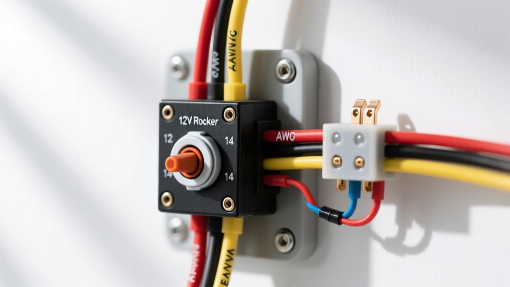
Understanding the 3 Pin Rocker Switch Wiring Diagram
When outfitting a truck, Jeep, or UTV with aftermarket accessories like off-road LED light bars, winches, or auxiliary air compressors, the 3 pin rocker switch wiring diagram is the foundational blueprint for a reliable circuit. Unlike a standard 2-pin Single Pole Single Throw (SPST) switch, a 3-pin illuminated rocker switch contains an internal indicator LED. This requires a dedicated ground path to illuminate the switch face when the circuit is closed, providing crucial visual feedback in low-light or off-road environments.
Executing a proper installation requires more than simply connecting wires to spade terminals. It demands adherence to automotive electrical standards, precise wire gauge selection, and an understanding of when to use a direct load versus a relay-driven configuration. This comprehensive guide will walk you through the exact pinout specifications, crimping methodologies, and relay integration techniques required for a professional-grade 12V DC installation.
Anatomy and Pinout of a 3-Pin Illuminated Switch
Most aftermarket 3-pin rocker switches (compatible with standard Carling V-Series cutouts) utilize 0.250-inch (6.35mm) male spade terminals on the rear housing. The terminals are typically laser-etched or stamped with specific symbols to denote their function. Misinterpreting these symbols is the leading cause of short circuits and melted switch housings in amateur installations.
| Pin Number | Terminal Marking | Electrical Function | Recommended Wire Color | Connection Destination |
|---|---|---|---|---|
| Pin 1 (Center) | + (or ACC/BAT) | 12V Power Input | Red | Fused 12V Source (Ignition or Battery) |
| Pin 2 (Top/Edge) | O (or Load) | Switched Power Output | Blue or White | Relay Coil (Pin 85) or Direct Load (+) |
| Pin 3 (Bottom/Edge) | - (or GND) | Internal LED Ground | Black | Chassis Ground or Battery Negative |
Expert Note: The internal LED is typically wired in parallel with the load output. This means Pin 3 only completes the circuit for the low-draw indicator light (usually 10mA to 20mA). It does not handle the amperage of the primary accessory load.
Essential Tools and Material Specifications
According to SAE J1128 standards for low-tension primary automotive cable, utilizing the correct wire gauge and insulation type is non-negotiable to prevent voltage drop and thermal runaway. Never use solid-core copper wire or household THHN wire; automotive environments require stranded, cross-linked polyethylene (XLPE) or PVC-insulated wire rated for 105°C to 125°C.
- Wire (Switch Pigtails): 16 AWG Stranded Automotive Primary Wire (GXL or TXL type).
- Wire (Relay Power/Load): 12 AWG or 10 AWG Stranded (depending on total amperage draw).
- Terminals: Nylon-insulated female spade connectors (16-14 AWG, Blue) with internal copper barrels.
- Crimping Tool: Ratcheting terminal crimper (ensures uniform compression and prevents strand pull-out).
- Heat Shrink: 3:1 shrink ratio, adhesive-lined polyolefin heat shrink tubing.
- Fuses: ATO/ATC standard blade fuses (sized to 125% of the continuous load amperage).
Direct Load vs. Relay Integration: Which Configuration?
Before cutting a single wire, you must calculate the total amperage of your accessory. A standard 3-pin rocker switch is mechanically rated for 10A to 20A at 12V DC. However, running high-amperage loads directly through the switch contacts causes arcing, which pits the internal copper contacts and increases electrical resistance over time.
| Configuration Type | Maximum Load | Best Use Case | Wiring Complexity |
|---|---|---|---|
| Direct Load | Up to 10A (Continuous) | Small LED rock lights, horn relays, low-draw solenoids. | Low (Switch in-line with load) |
| Bosch-Style Relay | 30A to 40A+ | LED light bars, winch contactors, air compressors, fuel pumps. | Medium (Switch triggers relay coil) |
For the remainder of this guide, we will detail the Bosch-style relay configuration, as it is the safest and most common method for off-road accessories, ensuring the switch only handles the minimal current required to energize the relay coil (typically under 0.2A).
Step-by-Step Installation Guide
Step 1: Sizing the Fuse and Power Source
Identify a suitable 12V power source. If the accessory should only operate when the vehicle is running, tap an ignition-switched circuit using a high-quality fuse tap. If the accessory requires constant power (e.g., a winch solenoid or auxiliary bus), connect directly to the battery's positive terminal using an appropriately sized ring terminal.
Calculate your fuse size using Ohm's Law (Amps = Watts / Volts). For a 120W LED light bar on a 13.8V running system: 120 / 13.8 = 8.69 Amps. Apply the 125% safety margin rule recommended by Littelfuse engineering guidelines: 8.69 x 1.25 = 10.86A. Therefore, a 15A ATO blade fuse is the correct specification. Always place the fuse within 8 inches of the power source.
Step 2: Terminating the Switch Pigtails
Cut three lengths of 16 AWG wire (Red, Blue, Black) long enough to route from the switch dashboard location to a centralized relay block in the engine bay. Strip 5/16" of insulation from each end.
Insert the bare copper strands into the brass barrel of the 16-14 AWG female spade terminal. Ensure no copper strands are splayed outside the barrel. Using a ratcheting crimper, compress the terminal until the ratchet releases. Perform a pull test; the wire should not separate from the terminal. Slide a piece of adhesive-lined heat shrink over the connection and apply heat until the adhesive oozes from the edges, creating a waterproof seal against under-dash humidity and condensation.
Step 3: Routing and Relay Coil Connections
Route the switch harness through the firewall using an existing rubber grommet to prevent chafing against sheet metal. At the engine bay relay block, make the following connections to a standard ISO mini relay:
Red Wire (Pin 1): Connect to a fused 12V constant or switched source.
Blue Wire (Pin 2): Connect to Relay Pin 85 (Relay Coil Ground/Trigger).
Black Wire (Pin 3): Connect to a clean, bare-metal chassis ground point. Secure with a star washer and torque to manufacturer specifications (typically 8-12 Nm) to prevent ground loop resistance.
Step 4: Completing the High-Current Load Circuit
The relay handles the heavy lifting. Wire the high-current side of the relay using 12 AWG or 10 AWG wire:
Relay Pin 30 (Common): Connect to the main battery positive via a heavy-duty inline fuse.
Relay Pin 87 (Normally Open): Connect to the positive terminal of your off-road light bar or accessory.
Relay Pin 86 (Coil Power): Connect to a 12V switched ignition source (this energizes the coil when the key is turned, allowing the rocker switch on Pin 85 to act as the ground trigger).
Troubleshooting Common 3-Pin Switch Failures
Even with a flawless understanding of the 3 pin rocker switch wiring diagram, environmental factors and minor errors can cause circuit anomalies. Use this diagnostic tree to isolate faults:
- Symptom: Accessory turns on, but switch LED does not illuminate.
- Cause: Open circuit on Pin 3.
- Fix: Test the Black wire continuity to the chassis. Clean the ground point of paint, rust, or powder coating. Ensure the spade terminal is fully seated on Pin 3.
- Symptom: Switch LED illuminates, but accessory does not turn on.
- Cause: Relay coil is not receiving power on Pin 86, or the high-current load circuit is blown.
- Fix: Use a digital multimeter to verify 12V at Relay Pin 86 when the ignition is on. Check the main high-amp fuse on Relay Pin 30.
- Symptom: Switch LED stays on even when the switch is in the OFF position.
- Cause: Backfeed voltage or reversed Pin 1 and Pin 2.
- Fix: Verify that the Red wire (Power In) is on the center pin, and the Blue wire (Load Out) is on the outer pin. If reversed, the internal LED circuit bypasses the mechanical switch toggle.
- Symptom: Switch housing is hot to the touch or smells like melting plastic.
- Cause: Severe voltage drop due to poor crimps, or running >15A directly through the switch without a relay.
- Fix: Immediately disconnect power. Inspect spade terminals for looseness. Transition to a relay-driven configuration as outlined by Made Electrical's wiring primers.
Final Inspection and Safety Verification
Before closing up the dashboard or securing the relay block, perform a final voltage drop test. With the accessory energized, place your multimeter probes on the battery positive post and the accessory's positive input terminal. A healthy circuit should exhibit a voltage drop of no more than 0.2V to 0.3V. If the drop exceeds 0.5V, you have excessive resistance in your crimps or your wire gauge is insufficient for the run length. Secure all wiring with split loom tubing and UV-resistant zip ties, keeping harnesses away from exhaust manifolds and steering shafts. A properly executed 3-pin rocker switch installation will provide years of reliable, weatherproof operation in the harshest off-road conditions.