Introduction to Yankee Auto Electric Reproduction Systems
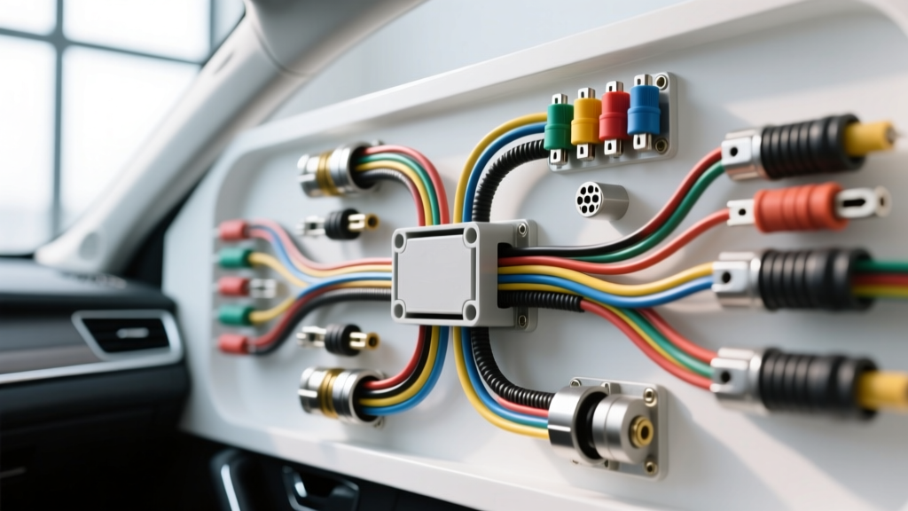
When restoring classic American vehicles from the 1960s through the 1980s, installers frequently rely on reproduction wiring systems modeled after original Yankee Auto Electric architectures. These harnesses replicate the factory bulkhead pass-throughs, ammeter routing, and fused junction blocks of classic Mopar, Ford, and GM muscle cars. However, replicating a 50-year-old electrical design also means replicating its inherent flaws. Classic harness designs are notorious for bulkhead connector oxidation, insufficient ground paths, and dangerous ammeter routing. This step-by-step troubleshooting flow is engineered for automotive electrical technicians to systematically isolate voltage drops, high-resistance faults, and routing failures in Yankee-style classic reproduction harnesses.
Phase 1: Bulkhead Connector and Firewall Pass-Through Inspection
The most critical failure point in any classic Yankee Auto Electric style harness is the firewall bulkhead connector. Factory designs often routed up to 32 individual circuits through a single multi-pin plastic housing. Over time, or during improper reproduction harness installation, these pins suffer from micro-movements, oxidation, and thermal expansion.
- Visual Inspection: Disconnect the battery negative terminal. Unbolt the bulkhead connector (typically a 1/4-inch hex screw in the center). Inspect the male and female terminals for green copper oxide or melted plastic housings.
- Pin Tension Testing: Use a terminal pin gauge to verify female receptacle tension. If a 14 AWG pin slides in without mechanical resistance, the receptacle is fatigued and must be replaced using an open-barrel Molex crimp tool.
- Dielectric Application: Apply a copper-based anti-oxidant paste (such as OxGard) to all high-current pins (10 AWG and 12 AWG) before reseating the bulkhead to prevent future galvanic corrosion.
Phase 2: Step-by-Step Diagnostic Decision Tree
Use the following symptom-based decision tree to isolate faults within the main chassis and dash harnesses.
Symptom A: Starter Solenoid Chatter or Slow Crank
- Step 1: Set your digital multimeter (DMM) to DC Volts. Connect the black lead to the battery negative post and the red lead to the starter solenoid 'S' terminal.
- Step 2: Have an assistant turn the ignition key to the 'Crank' position. Read the voltage.
- Step 3 (Diagnosis): If voltage at the 'S' terminal is below 9.5V, you have a voltage drop on the ignition switch feed. In classic Yankee harnesses, this is typically a Pink 14 AWG wire routing from the ignition switch, through the bulkhead (Pin 4), to the starter relay.
- Step 4 (Resolution): Perform a voltage drop test across the bulkhead Pin 4. If the drop exceeds 0.1V, extract the pin, clean the terminal, and re-crimp. If the wire is intact but voltage is still low, install a 30A Bosch-style relay triggered by the Pink 14 AWG wire to carry the heavy solenoid load directly from the battery via a new 10 AWG feed.
Symptom B: Headlights Dim When Braking or Using Heater
- Step 1: This indicates a shared ground return path overload or a failing bulkhead ground pin. Classic harnesses often rely on the Light Green 18 AWG or Black 14 AWG wires passing through the bulkhead to complete dash and lighting circuits.
- Step 2: Turn on the headlights and heater blower motor. Measure the voltage drop between the engine block and the negative battery post. It should be less than 0.05V.
- Step 3 (Diagnosis): If the engine ground is good, measure the voltage drop between the dash chassis and the battery negative. A reading above 0.2V confirms a degraded firewall ground strap or corroded bulkhead ground pins.
- Step 4 (Resolution): Bypass the bulkhead ground pins entirely. Run a dedicated 10 AWG black ground wire from a clean, bare-metal point on the engine block directly to the dash instrument cluster housing, securing it with a star washer and tightening to 15 in-lbs.
Symptom C: Intermittent Wiper or Heater Motor Failure
- Step 1: These high-draw accessories usually run on 12 AWG Orange or Dark Blue feeds in classic harnesses.
- Step 2: Wiggle the harness at the junction block and bulkhead while the motor is commanded on.
- Step 3 (Resolution): If the motor cuts out, the junction block spade terminal is loose. Solder the spade connection or replace the junction block with a modern sealed fuse block, upgrading the circuit protection to an ATO blade fuse.
Phase 3: Ammeter Wiring and Bypass Diagnostics
The most dangerous aspect of the original Yankee Auto Electric architecture—particularly in 1960s and 1970s Mopar and Ford designs—is the routing of the entire alternator output through the dashboard ammeter. This forces up to 60 amps of continuous current through the dash harness via two 10 AWG Red and Black wires. If the bulkhead connector develops resistance, it generates enough heat to melt the firewall and cause a catastrophic electrical fire.
The MAD Bypass Troubleshooting Flow:
- Inspect the back of the dash ammeter. If the insulation on the 10 AWG feed wires is brittle, cracked, or shows signs of thermal melting, immediate bypass is required.
- Disconnect the ammeter feeds and join the two original 10 AWG harness wires together using a sealed, adhesive-lined heat shrink butt connector. This restores power to the rest of the dash harness.
- Run a new 8 AWG primary cable (meeting SAE J1128 standards) directly from the alternator output stud to the positive battery terminal.
- Install a 50A Mega Fuse or fusible link within 6 inches of the battery connection on this new 8 AWG bypass wire.
- Install a modern digital voltmeter in the dash to monitor system health, as the original ammeter is now bypassed and inactive.
Classic Harness Wire Specification & Pinout Chart
Reference this chart when probing the main firewall bulkhead connector on standard classic reproduction harnesses.
| Circuit Function | Wire Color | AWG Size | Bulkhead Pin | Max Voltage Drop |
|---|---|---|---|---|
| Main Battery Feed | Red | 10 AWG | Pin 1 | 0.10V |
| Ignition Switch Feed | Pink | 14 AWG | Pin 4 | 0.15V |
| Headlight Feed | Dark Blue | 12 AWG | Pin 6 | 0.10V |
| Dash / Tail Lamps | Light Green | 18 AWG | Pin 8 | 0.20V |
| Instrument Cluster | Orange | 18 AWG | Pin 12 | 0.20V |
Phase 4: Ground Path Validation and Final Testing
A classic harness is only as reliable as its ground paths. Yankee-style harnesses rely heavily on 'star grounding' or localized grounding to the chassis. When troubleshooting erratic gauge behavior or dim lighting, always verify the ground before replacing components.
Use a DMM to measure resistance between the component housing (e.g., tail light housing, heater motor case) and the negative battery post. Resistance must read less than 0.5 ohms. If resistance is higher, remove the grounding screw, clean the chassis contact point down to bare metal using a wire wheel, apply a thin layer of dielectric grease over the terminal to prevent rust, and secure with a new stainless steel star washer. Torque chassis ground bolts to 12-15 ft-lbs to ensure vibration resistance.
For comprehensive testing procedures and advanced relay integration, refer to the Haynes Automotive Electrical Testing Guidelines. For deep-dive technical schematics on classic ammeter elimination and alternator upgrades, consult the MAD Electrical Ammeter Bypass Technical Archive. By following this structured flow, technicians can transform an aging reproduction harness into a reliable, fire-safe electrical system capable of supporting modern accessory loads.