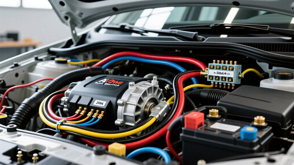
Project Overview: The A One Auto Electrics High-Amp Blueprint
When executing a high-amperage charging system overhaul for overland, off-road, or heavy-towing applications, the A One Auto Electrics methodology has become the benchmark for professional modification projects. Stock alternators, typically rated between 90A and 130A, rapidly fail when subjected to the continuous parasitic draws of modern auxiliary lighting, 12V refrigeration, winches, and high-wattage inverters. Upgrading to a 200A–300A high-output alternator is only half the battle; the true challenge lies in the wiring architecture. If you are planning a one auto electrics build that relies on high continuous amperage, strict adherence to AWG standards, redundant grounding, and isolated voltage sensing is non-negotiable.
This comprehensive guide details the exact wiring specifications, pin configurations, and termination protocols required to safely route 250+ amps from your alternator to a dual-battery setup without inducing voltage drop, thermal runaway, or alternator whine.
Component Selection & Wire Gauge Sizing
The foundation of any high-amp upgrade is selecting the correct cable. The A One Auto Electrics standard strictly forbids the use of CCA (Copper-Clad Aluminum) wire. CCA has a higher resistance than pure copper and is prone to galvanic corrosion and snapping under engine bay vibration. You must use OFC (Oxygen-Free Copper) or tinned marine-grade copper. According to the SAE J1128 standard for low-tension primary cable, wire sizing must account for both the maximum current load and the total length of the circuit to maintain a voltage drop of less than 3%.
| Circuit Path | AWG Size | Wire Type | Protection / Fuse | Terminal Type |
|---|---|---|---|---|
| Alternator B+ to Primary Battery | 1/0 AWG | OFC / Tinned | 300A ANL or Class T | 3/8' Tinned Ring (5/16' if M8 stud) |
| Primary to Secondary Battery (VSR) | 1/0 AWG | OFC / Tinned | 250A ANL (at each end) | 3/8' Tinned Ring |
| Alternator Case to Chassis Ground | 4 AWG | OFC Braided Strap | None (Direct Ground) | M10 / M8 Ring Terminal |
| Voltage Sense Wire | 12 AWG or 10 AWG | TXL / GXL | 5A ATO Blade Fuse | 1/4' Spade or Ring |
| Excitation / Ignition Wire | 14 AWG | TXL | 10A ATO Blade Fuse | Weather-Pack / Deutsch Pin |
3-Wire Alternator Pinout and Excitation Wiring
High-output alternators typically utilize a 3-wire or 4-wire regulator plug to manage field excitation and voltage sensing. Incorrectly wiring the sense or excitation pins will cause the alternator to either overcharge (boiling the battery) or undercharge (resulting in a dead battery and stator burnout). Below are the pinouts for the two most common high-amp upgrade cores: the Denso SC series and the GM CS130D.
Denso SC Series (Common in Toyota/Lexus/Off-Road Upgrades)
- Pin L (Light): Connects to a switched 12V ignition source. This signals the internal voltage regulator to wake up and begin charging. Route a 14 AWG wire from an ignition-spliced fuse box circuit.
- Pin IG (Ignition): Connects directly to battery positive (B+) via a 10A inline fuse. This provides the initial field current required to magnetize the rotor before the alternator begins self-exciting.
- Pin S (Sense): The most critical wire. This must be routed directly to the positive terminal of the battery, not to the alternator output post. If connected to the alternator post, the regulator will compensate for zero voltage drop, causing the battery to receive less than 14.2V due to the resistance of the 1/0 AWG cable and the ANL fuse.
GM CS130D / AD244 Series
- Pin L (Lamp): Switched ignition 12V. Turns on the regulator and can optionally drive a dash warning light via a 330-ohm resistor.
- Pin S (Sense): Direct battery positive connection. Must be fused at 5A within 7 inches of the battery terminal.
- Pin F (Field): Pulse Width Modulated (PWM) output. Used by the ECU to monitor alternator load and adjust engine idle speed. If bypassing the ECU for a standalone swap, this pin is typically left unconnected or tied to a diagnostic LED.
Step-by-Step Routing and Termination Protocol
Proper termination is where most DIY high-amp builds fail. A poorly crimped 1/0 AWG terminal will generate immense heat under a 150A continuous load, potentially melting the insulation and causing an engine bay fire.
- Stripping the Cable: Use a dedicated 1/0 AWG wire stripper. Do not score the copper strands with a utility knife, as nicked strands create micro-fractures that will snap under engine vibration. Strip exactly 1-1/8 inches of insulation.
- Flux and Crimping: Apply a small amount of rosin-based electrical flux to the bare copper before inserting it into the tinned copper ring terminal. Use a 12-ton hydraulic crimper with a hex-crimp die. Hex crimps provide a uniform, cold-weld compression that is vastly superior to indent crimps for high-amperage applications.
- Sealing the Termination: Slide a piece of 3:1 ratio, dual-wall polyolefin heat shrink over the terminal before crimping. Once crimped, apply heat evenly. The inner layer of marine-grade adhesive must melt and extrude slightly from the edges, creating a waterproof seal that prevents capillary action from drawing moisture into the copper strands.
- Routing: Route the 1/0 AWG B+ cable away from exhaust manifolds and moving linkages. Secure the cable every 8 inches using UV-resistant, stainless-steel cushion clamps. Do not use standard zip-ties, which become brittle and fail under high under-hood temperatures.
Voltage Sense and Dual Battery Isolator Integration
When integrating a Voltage Sensitive Relay (VSR) or a DC-DC charger for a secondary auxiliary battery, the sense wire architecture must be flawless. The A One Auto Electrics standard dictates that the alternator's sense wire monitors the starting battery. The VSR should be mounted as close to the primary battery as possible. Use 1/0 AWG OFC wire to bridge the primary battery positive to the VSR input, and another 1/0 AWG run from the VSR output to the secondary battery. Install a 250A ANL fuse within 7 inches of the secondary battery positive terminal to protect the auxiliary circuit in the event of a dead short.
Grounding Architecture and Chassis Preparation
High-output alternators require a dedicated, heavy-duty ground path. Relying solely on the alternator's mounting brackets to ground to the engine block is insufficient and will cause alternator whine and diode failure. Run a dedicated 4 AWG braided copper ground strap from the alternator casing to the engine block or chassis. Preparation Steps: 1. Use a 3M Roloc disc to remove all paint, powder coating, and rust from the chassis mounting point down to bare, shiny metal. 2. Apply a thin layer of Noalox (zinc-dust anti-oxidant compound) to the bare metal to prevent galvanic corrosion between the copper terminal and the steel/aluminum chassis. 3. Torque the M10 ground bolt to 25 Nm (18 lb-ft) to ensure a gas-tight mechanical connection.
Diagnostic Troubleshooting and Real-World Failure Modes
Even with meticulous planning, high-amp systems can exhibit faults. Use a digital multimeter set to DC Millivolts (mV) to perform voltage drop testing. According to Blue Sea Systems circuit guidelines, a healthy high-amp cable should exhibit a voltage drop of less than 0.1V (100mV) under full load.
Symptom-Cause-Fix Decision Tree
- Symptom: Battery voltage reads 14.4V at the alternator B+ post, but only 13.6V at the battery terminals while under load.
Cause: Excessive resistance in the B+ cable, corroded ANL fuse contacts, or an undersized wire gauge.
Fix: Perform a voltage drop test across the ANL fuse and cable. Replace CCA wire with OFC, and ensure ANL fuse bolts are torqued to 12 Nm. - Symptom: Alternator whine heard through the stereo system, increasing with engine RPM.
Cause: Poor alternator case grounding or the voltage sense wire routed parallel to the RCA/audio signal cables, inducing electromagnetic interference (EMI).
Fix: Install the dedicated 4 AWG braided ground strap and reroute the 12 AWG sense wire on the opposite side of the engine bay from audio signal lines. - Symptom: Alternator does not charge until the engine is revved past 2,500 RPM.
Cause: The excitation (Pin L / IG) wire is losing voltage due to a poor ignition splice, failing to provide the minimum 9V required to energize the rotor field.
Fix: Check the ignition splice. Use a relay triggered by the ignition switch to send a clean, full 12V battery signal directly to the alternator excitation pin.
For further diagnostic procedures on testing alternator ripple current and diode health, refer to the Haynes alternator testing tutorials. By adhering strictly to these heavy-duty wiring protocols, your high-amp charging system will deliver reliable, continuous power in the most demanding off-road and overland environments.