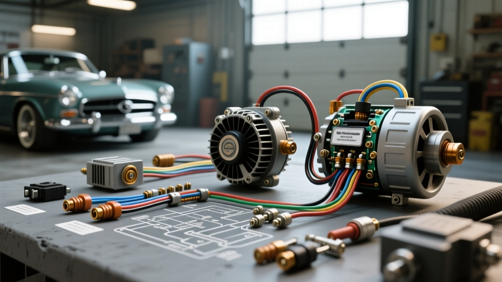
Introduction to the Woodrow Auto Electric Method
When building a classic restomod or upgrading a vintage vehicle with modern high-draw accessories, standard factory wiring diagrams quickly become obsolete. The methodology often referred to in custom restomod circles as the Woodrow Auto Electric standard prioritizes extreme voltage drop mitigation, oversized grounding architectures, and dedicated relay circuits for high-amperage accessories. This approach ensures that high-output alternators and electric AC compressors receive clean, stable voltage, preventing the dreaded 'dimming lights' or 'chattering clutch' symptoms common in amateur builds.
This practical how-to guide will walk you through the exact installation procedures, wire gauge selections, and pin configurations required to execute a bulletproof alternator and electric AC compressor upgrade using these proven automotive electrical principles. Whether you are wiring a 1969 Camaro or a 1972 C10 pickup, adhering to these SAE International J1128 wire specifications will ensure your electrical system operates safely and efficiently.
Phase 1: High-Output Alternator Wiring Architecture
Upgrading from a classic 65-amp GM 10SI or Ford 1G alternator to a modern 200A+ 1-wire or 3-wire smart alternator requires a complete overhaul of the charge wire and grounding system. Pushing 200 amps through a factory 10 AWG charge wire will result in catastrophic melting and potential vehicle fire. The Woodrow Auto Electric method dictates the use of Oxygen-Free Copper (OFC) welding cable and redundant chassis grounding.
Charge Wire and Grounding Specifications
| Circuit Function | Wire Gauge (AWG) | Wire Type / Color | Max Length (One Way) | Fusing Requirement |
|---|---|---|---|---|
| Main B+ Charge Wire | 1/0 AWG | OFC Red Welding Cable | 60 inches | 250A ANL / Mega Fuse |
| Alternator Sense Wire (3-Wire) | 10 AWG | Primary White | Direct to Battery (+) | 15A Inline ATO |
| Engine to Chassis Ground | 2 AWG | Braided Copper Strap | 18 inches | N/A |
| Alternator Case Ground | 4 AWG | OFC Black | 12 inches | N/A |
Step-by-Step Alternator Installation
- Remove Factory Harness: Disconnect the battery. Remove the factory 10 AWG charge wire and the 2-pin/3-pin plastic regulator connector. Inspect the alternator bracket mounting surfaces. Use a wire wheel to remove all paint, rust, and powder coating from the alternator mounting ears and engine block bracket to ensure bare metal-to-metal contact.
- Install the Mega Fuse: Mount a 250A Mega fuse holder within 18 inches of the starter solenoid or main battery positive terminal. Crimp the 1/0 AWG red cable using a hydraulic crimper and adhesive-lined heat shrink ring terminals. Never use solder on high-amp automotive battery cables, as solder joints are brittle and prone to cracking under engine vibration.
- Route the Main Charge Wire: Route the 1/0 AWG cable away from exhaust headers. If passing near sharp metal edges, use split-loom corrugated tubing and friction tape. Connect the ring terminal to the alternator B+ post (M8 stud). Torque the M8 nut to exactly 75 in-lbs. Over-torquing can strip the aluminum alternator housing threads.
- Wire the Sense Circuit (3-Wire Alternators Only): If using a 3-wire smart alternator, run a 10 AWG white wire from the alternator 'S' (Sense) terminal directly to the battery positive post or main starter junction block. This ensures the internal regulator reads true battery voltage, not the voltage dropped across the heavy charge wire.
- Establish Redundant Grounds: Bolt a 2 AWG braided ground strap from the engine block to the chassis rail. Torque the mounting bolts to 25 ft-lbs. Add a dedicated 4 AWG black wire from the alternator case to the engine block to guarantee the regulator has a flawless ground reference.
Phase 2: Electric AC Compressor Integration
Classic vehicles converted to modern Restomod configurations often utilize electric AC compressors (such as the Sanden SD7 or brushless Davies Craig units) to free up engine bay space or eliminate parasitic drag. These compressors draw massive inrush currents—often 35 to 45 amps upon clutch engagement. Wiring an electric AC compressor directly to a dashboard toggle switch or a standard 30-amp HVAC relay will result in melted contacts and compressor failure.
Following Vintage Air Technical Manuals and heavy-duty relay protocols, you must isolate the high-draw compressor clutch circuit from the vehicle's low-current dash wiring.
Electric AC Compressor Relay Pinout (Bosch-Style 5-Pin)
| Relay Pin | Function | Wire Gauge & Color | Destination / Source |
|---|---|---|---|
| Pin 30 | High Amp Power In | 8 AWG Red | Battery (+) via 50A MAXI Fuse |
| Pin 87 | High Amp Power Out | 10 AWG Red | AC Compressor Clutch (+) |
| Pin 86 | Trigger Signal In | 14 AWG Pink | AC Thermostat / Binary Switch |
| Pin 85 | Relay Coil Ground | 14 AWG Black | Clean Chassis Ground |
| Pin 87a | Normally Closed | Not Used | Tape off and secure |
Step-by-Step AC Compressor Wiring
- Install the MAXI Fuse: Run an 8 AWG red wire from the main battery distribution block to a 50A MAXI fuse holder, then to Pin 30 on a heavy-duty 40A+ Bosch-style relay. Secure the relay in a weatherproof enclosure away from direct engine heat.
- Wire the Clutch Load: Run a 10 AWG red wire from Pin 87 to the AC compressor clutch connector. For modern brushless compressors utilizing a 3-pin Deutsch DT controller, Pin 87 will supply the 12V+ to Pin A on the Deutsch connector, while Pin B grounds to the chassis and Pin C receives the PWM signal from the cabin thermostat.
- Wire the Trigger Circuit: Connect a 14 AWG pink wire from Pin 86 to your AC thermostat switch or binary safety switch. This low-amp circuit only needs to energize the relay coil (drawing less than 0.2 amps), protecting your vintage dashboard switches from heat degradation.
- Ground the Relay and Compressor: Terminate Pin 85 with a 14 AWG black wire to a clean, unpainted metal surface on the firewall. Ensure the AC compressor body itself is grounded via a dedicated 10 AWG braided strap to the engine block or chassis, as rubber isolation mounts will otherwise prevent the clutch coil from completing its ground circuit.
Troubleshooting Common Restomod Electrical Gremlins
Even with meticulous wiring, high-amperage restomod systems can exhibit quirks. Use this diagnostic decision tree to resolve common issues encountered after installing high-output alternators and electric AC compressors.
Symptom: Headlights Dim and AC Compressor Chatters at Idle
- Cause 1: Alternator Pulley Ratio Mismatch. High-output alternators require high rotor RPMs to reach their rated amperage. If you retained the factory 6-groove serpentine pulley, the alternator may only be spinning at 1,800 RPM at idle, failing to produce enough current to run the electric AC clutch and headlights simultaneously.
- Fix: Install an overdrive alternator pulley (e.g., reducing the alternator pulley diameter from 2.4 inches to 1.9 inches) to achieve a 3:1 crank-to-alternator ratio. Consult Powermaster Performance Tech Support for specific pulley sizing based on your crankshaft pulley diameter.
- Cause 2: AC Ripple Voltage. A failing diode trio inside the alternator or a poor ground path can introduce AC ripple voltage into the DC system, causing the AC clutch relay to rapidly cycle on and off (chatter).
- Fix: Set your digital multimeter to AC Millivolts (mV). Place the probes on the battery terminals with the engine running and the AC engaged. If the AC ripple exceeds 50mV, inspect the 2 AWG engine-to-chassis ground strap and the alternator case ground. Replace any corroded terminals.
Symptom: Alternator B+ Terminal Melting or Discoloring
- Cause: High resistance at the crimp joint or inadequate torque on the M8 terminal nut. Vibration has caused the ring terminal to loosen, creating an arc-welding effect that generates extreme heat.
- Fix: Cut off the damaged terminal. Strip the 1/0 AWG cable back to clean copper. Use a closed-barrel hydraulic crimper and seal with 3M adhesive-lined heat shrink. Re-torque the M8 nut to 75 in-lbs and apply a dab of dielectric grease over the exposed threads to prevent corrosion.
Final Safety and Torque Inspections
Before reconnecting the battery and performing the initial engine start, execute a final physical audit of your Woodrow Auto Electric style wiring harness. Tug-test every crimped ring terminal to ensure the wire does not slip out of the barrel. Verify that all battery cables are routed at least 4 inches away from exhaust manifolds. Finally, ensure your ANL or Mega fuses are properly seated and that the protective covers are snapped into place. A properly executed high-amperage wiring system will not only support your electric AC compressor and high-output alternator but will provide the reliable, spark-free foundation required for modern EFI and digital ignition systems.