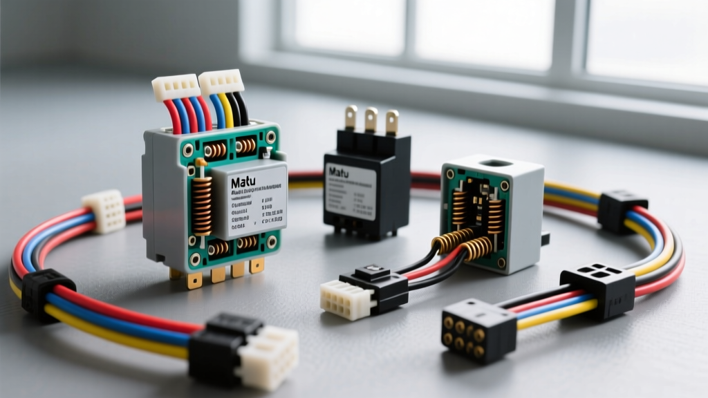
Demystifying the Matsu Auto Electric Stamp
When beginners and DIY enthusiasts begin tearing into the fuse boxes of 1990s and 2000s Japanese vehicles—such as the Toyota 4Runner, Honda Civic, or Subaru Outback—they frequently encounter a confusing stamp on the black plastic casing of relays, alternators, and blower motor resistors: MATSUSHITA or MATSU. If you have been searching for information on a matsu auto electric component, you are looking at the legacy of Matsushita Electric Industrial Co., the manufacturing giant that officially changed its name to Panasonic Corporation in 2008.
For decades, Matsushita was the premier OEM supplier for Asian automakers. Their electrical components are renowned for extreme longevity, but after 20 years of heat cycling, the internal solder joints, coil windings, and plastic connector housings can degrade. Understanding the fundamental architecture of these components is the first step toward effective diagnosis and repair. This guide breaks down the wiring standards, pin configurations, and testing procedures for the most common Matsushita automotive electrical systems.
Standard Matsushita OEM Micro Relays
The most ubiquitous matsu auto electric component is the ISO micro relay. Found in engine bay junction blocks and interior dash fuse panels, these relays act as heavy-duty electromagnetic switches. They allow a low-current circuit (like a headlight switch or ECU signal) to control a high-current circuit (like cooling fans or fuel pumps) without routing thick cables through the dashboard.
Matsushita typically manufactured these in two variants: the standard 4-pin (Single Pole Single Throw - SPST) and the 5-pin (Single Pole Double Throw - SPDT) changeover relay. Below is the standard pinout and typical OEM wire color coding used in conjunction with these relays.
4-Pin SPST Micro Relay Pinout Table
| Pin Number | Terminal Function | Circuit Type | Typical OEM Wire Color | Recommended AWG |
|---|---|---|---|---|
| 85 | Coil Ground | Control (Low Amp) | Black/White Tracer | 18 AWG |
| 86 | Coil Power (Switched) | Control (Low Amp) | Blue/Red Tracer | 18 AWG |
| 30 | Common Power Input | Load (High Amp) | White/Black Tracer | 12 AWG |
| 87 | Normally Open (NO) Output | Load (High Amp) | Green or Red | 12 AWG |
Understanding the 5-Pin Changeover Variant
If your matsu auto electric relay has a fifth pin, it is designated as 87a (Normally Closed). In a resting state, power flows from Pin 30 to Pin 87a. When the coil is energized via Pins 85 and 86, the internal armature shifts, breaking the 87a connection and making the 87 connection. These are commonly used in OEM alarm systems, horn circuits, and daytime running light (DRL) modules. Matsushita often integrated a internal flyback diode across pins 85 and 86 in these 5-pin relays to suppress voltage spikes when the coil de-energizes, protecting sensitive ECU transistors.
Matsushita Alternator Voltage Regulators
Another cornerstone of the matsu auto electric legacy is the internal voltage regulator found on 1990s Toyota and Lexus alternators. Unlike modern LIN-bus controlled alternators, these utilized a simple, highly reliable 3-pin connector plug. Troubleshooting charging system issues on these vehicles requires understanding the specific function of each wire in this harness.
3-Pin Alternator Regulator Connector
| Terminal | Function | Typical Wire Color | Diagnostic Notes |
|---|---|---|---|
| IG (Ignition) | Wakes up the regulator | Black/Orange | Should read 12V+ with key in the ON position. Fed via the ignition switch fuse. |
| L (Lamp) | Dashboard charge indicator | Yellow/Red | Provides a ground path to illuminate the battery light when the engine is off. Should read 12V+ when engine is running. |
| S (Sense) | Battery voltage feedback | White/Red | Critical: Routes directly to the battery positive terminal to measure true system voltage, bypassing alternator wire voltage drop. |
Expert Tip: A common failure mode on these vehicles is a broken 'S' (Sense) wire. If the S terminal loses connection to the battery, the regulator defaults to a failsafe mode, often overcharging the system to 15V+ or undercharging at 13V, depending on the exact Matsushita firmware revision. Always check the S wire continuity directly to the battery positive post before replacing the alternator.
Beginner Troubleshooting: Testing a Matsu Relay
Before replacing a suspect component, verify its failure using a digital multimeter (DMM). According to the Haynes Automotive Relay Testing Guide, a systematic approach prevents unnecessary parts swapping.
- Test the Coil Resistance (Ohms): Set your DMM to the Ohms (Ω) setting. Place the probes on Pins 85 and 86. A healthy Matsushita micro relay coil will typically read between 65 and 85 ohms. If you read 'OL' (Open Loop), the internal copper winding is broken. If you read near 0 ohms, the coil is shorted.
- Test the Switch Continuity: Set the DMM to the continuity (beep) setting. Place probes on Pins 30 and 87. It should read 'OL' (no continuity). Now, use a pair of jumper wires to apply 12V power from the vehicle battery to Pins 86 and 85. You should hear a distinct 'click' from the relay, and your multimeter should beep, indicating continuity between 30 and 87.
- Check for Voltage Drop: If the relay clicks but the accessory (e.g., cooling fan) doesn't run, the internal carbon contacts may be pitted. With the relay energized and the accessory running, measure DC voltage between Pin 30 and Pin 87. A healthy relay will show less than 0.1V drop. Anything above 0.3V indicates high internal resistance and a failing relay.
Upgrading and Rewiring OEM Matsu Harnesses
When a matsu auto electric relay socket becomes brittle and melts due to high resistance, you must replace the pigtail. Do not simply twist wires together and use electrical tape. Adhering to the SAE J1128 Low Tension Primary Cable Standard ensures your repair will survive the harsh engine bay environment.
- Wire Selection: Use cross-linked polyethylene (XLPE) insulated wire, such as TXL or GXL, which withstands temperatures up to 125°C. Standard PVC wire will melt near exhaust manifolds.
- Terminal Crimping: Matsushita sockets utilize standard 6.3mm (1/4 inch) spade terminals. Use an open-barrel crimp tool (like the TE Connectivity CERTI-CRIMP) rather than a generic crushing tool. A proper open-barrel crimp creates a gas-tight connection that prevents moisture intrusion and copper oxidation.
- Sealing: Use adhesive-lined dual-wall heat shrink tubing. The inner adhesive layer melts and seals the wire strands, preventing capillary action from wicking water into the harness.
Frequently Asked Questions
Can I use a standard Bosch-style relay to replace a Matsu relay?
In most cases, yes. The ISO micro footprint is standardized. However, you must check for an internal diode or resistor. If the OEM Matsushita circuit relies on a flyback diode to protect an ECU driver, installing a standard Bosch relay without a diode can cause voltage spikes that destroy the ECU transistor. Always check the schematic or look for the diode symbol printed on the relay casing.
Why is my Matsu blower motor resistor melting?
Blower motor resistors operate on the principle of converting excess voltage into heat. If the blower motor bearings are seizing, the motor draws excessive amperage. This higher current forces the Matsushita resistor coils to dissipate more heat than designed, melting the plastic housing. Always measure the blower motor amp draw (should be under 10A on high speed) before installing a new resistor.
Conclusion
Encountering a matsu auto electric stamp is a hallmark of working on reliable, well-engineered Japanese vehicles. By understanding the standardized pinouts, respecting the specific wire gauges, and utilizing proper diagnostic procedures, beginners can confidently troubleshoot and repair these foundational electrical systems. For further reading on OEM electrical architectures, consult the Panasonic Automotive Systems heritage archives and your vehicle's specific Factory Service Manual (FSM).