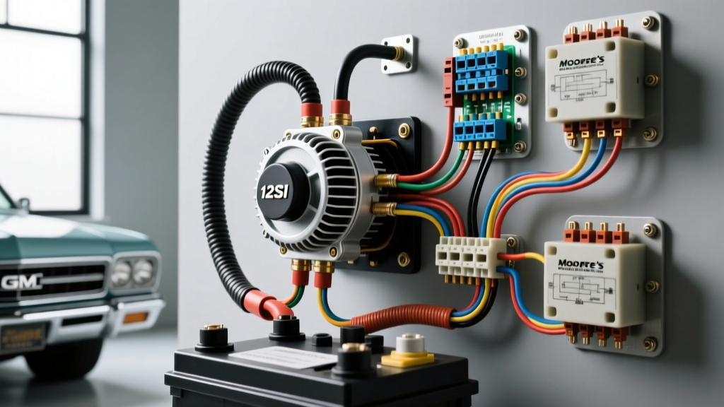
The Restomod Charging Dilemma
When converting a classic 1968-1972 GM A-Body, F-Body, or X-Body to run modern electronic fuel injection (EFI), electric cooling fans, and high-wattage audio, the factory charging system becomes a critical bottleneck. Original equipment Delco DN-series alternators max out at a dismal 37 to 60 amps and rely on an external voltage regulator mounted on the radiator support. These external regulators are notorious for connector corrosion, voltage drop, and premature brush wear. To support a modern 100+ amp electrical architecture, restomod builders frequently turn to the methodology championed by classic car electrical specialists—often referred to on the bench as the Moore's Auto Electric method. This approach prioritizes high-output internal regulation, heavy-gauge SAE-compliant cable routing, and precise Packard connector termination to eliminate voltage drop and prevent harness fires.
The 12SI Internally Regulated Swap
The cornerstone of this upgrade is swapping the externally regulated DN alternator for a Delco 12SI (System Integral) internally regulated alternator. The 12SI is a workhorse, widely available in 94-amp to 105-amp configurations, with high-output aftermarket stators pushing 140 amps. Because the regulator is housed inside the alternator case, it reads temperature and voltage directly at the source, eliminating the 14-gauge sense wires running to the firewall that plagued the DN setup.
Pinout and Packard Connector Termination
The 12SI utilizes a rectangular 2-pin connector housing Delphi/Packard 56-series female terminals. Proper crimping is non-negotiable; using pliers instead of a dedicated ratcheting crimper (like the Delphi 12014254 or equivalent) will result in high resistance and melted housings. Below is the exact pinout and wiring specification for the 12SI regulator plug.
| Pin | Label | Function | Wire Gauge (AWG) | Destination / Routing |
|---|---|---|---|---|
| 1 | L (Lamp/Excite) | Provides initial rotor excitation and grounds through the dash indicator bulb. | 12 AWG (TXL) | Ignition switch (RUN). Must route through a 194 bulb or a 10-ohm 2W resistor if using LED dash lights. |
| 2 | F (Field/Sense) | Remote voltage sense. Reads true system voltage to adjust regulator output. | 12 AWG (TXL) | Main battery positive post or primary bus bar. Do NOT jumper to the alternator BAT post. |
Main Output Wire: SAE J1128 Compliance and Routing
The most common failure point in DIY alternator upgrades is undersizing the main charge wire. The factory 10 AWG wire used on 1960s GM vehicles will melt if subjected to the continuous 90+ amp output of a 12SI alternator. The Moore's Auto Electric standard dictates upgrading the main charge cable to 4 AWG SGX (Standard Cross-Linked) or SGT battery cable, in strict accordance with SAE J1128 high-temperature automotive cable specifications. SGX wire features a thinner, highly abrasion-resistant insulation compared to standard PVC, allowing it to handle engine bay heat while remaining flexible enough to route through tight chassis channels.
Bypassing the Factory Horn Relay Bus
In classic GM wiring, the alternator's main output feeds the horn relay bus bar on the driver's side inner fender, which then acts as the main junction for the vehicle's electrical loads. The factory 10 AWG wire running from this bus bar across the radiator support to the battery is entirely inadequate for a 140-amp system. The upgrade requires running a continuous 4 AWG cable from the alternator BAT post, across the engine bay (safely loomed and secured away from exhaust headers), directly to the starter solenoid or a modern mega-fuse block. A secondary 4 AWG ground cable must also be installed from the alternator mounting bracket to the engine block to ensure the case is properly grounded, preventing stray voltage from seeking a path through the throttle cable or hood hinges.
Exciter Circuit and Dash Light Integration
Pin 1 (L) on the 12SI regulator requires a specific resistance to 'excite' the alternator's rotor and begin charging. In a factory setup, this is achieved by routing the wire through the dashboard 'GEN' or 'ALT' idiot light bulb. If your restomod uses an LED dash cluster or an aftermarket digital gauge panel, the LED will not provide the necessary resistance or current bleed, resulting in an alternator that will not charge until the engine is revved to 2,500+ RPM. To solve this, you must wire a 1N5404 diode in series with the exciter wire to prevent back-feeding, or install a 10-ohm, 2-watt ceramic resistor in parallel with the ignition feed to simulate the incandescent bulb's resistance. For a comprehensive look at integrating these circuits into modern chassis harnesses, builders often reference the Painless Performance classic GM chassis harness manuals, which detail proper relay and resistor placement.
Remote Voltage Sense (Pin 2) Best Practices
Pin 2 (F) is the remote voltage sense wire. Its sole job is to tell the internal regulator what the actual voltage is at the vehicle's main electrical distribution point. If you jumper Pin 2 directly to the alternator's BAT post, the regulator will only compensate for voltage drop inside the alternator itself, ignoring the voltage drop occurring across the 15 feet of wiring leading to your EFI computer and fuel pumps. Always route a dedicated 12 AWG sense wire from Pin 2 directly to the positive terminal of the battery or the main positive bus bar feeding your EFI relays. This ensures the alternator ramps up its output to overcome chassis wire resistance, maintaining a rock-solid 14.2V at the fuel pump relays.
Circuit Protection: Fusible Links vs. ANL Fuses
Running a 4 AWG main charge wire directly to the battery without overcurrent protection is a severe fire hazard. In the event of an alternator diode trio failure or a dead short to the chassis, the battery will dump hundreds of amps into the wire. The traditional GM method utilizes a fusible link. The golden rule of fusible links, as documented by classic GM wiring authorities like MAD Enterprises, is that the fusible link must be exactly four wire gauges smaller than the wire it protects. Therefore, a 4 AWG main charge wire requires an 8 AWG fusible link. However, for modern restomods, many builders prefer mounting a marine-grade 150-amp ANL fuse block within 12 inches of the battery positive terminal. This provides easily replaceable, highly reliable circuit protection without the need to splice and solder fragile fusible link wire in the engine bay.
Mechanical Mounting and Torque Specifications
Electrical upgrades must be matched by mechanical precision. When mounting the 12SI alternator to the classic GM cast-iron block, the bracketry must be perfectly aligned to prevent belt squeal and premature bearing failure. The long adjustment bolt (typically 3/8-16 or M10 depending on the water pump configuration) should be torqued to 30-35 lb-ft. The main pivot bolt at the base of the alternator, which threads directly into the cast-iron block or front cover, must be torqued to 37 lb-ft using a high-strength thread locker. Ensure the pulley groove perfectly aligns with the crankshaft and water pump pulleys using a laser alignment tool or a straight-edge across the pulley faces; even a 2mm misalignment will shred a Gates V-belt in under 500 miles.
Summary of Upgrade Specifications
| Component | Specification / Part Type | Notes |
|---|---|---|
| Main Charge Wire | 4 AWG SGX Stranded Copper | Must handle continuous 120A+ load without excessive voltage drop. |
| Alternator Ground | 4 AWG to Engine Block | Prevents stray voltage and ensures proper regulator reference. |
| Regulator Plug | Delphi Packard 56-Series | Requires proper ratcheting crimper; never solder terminals. |
| Main Circuit Protection | 8 AWG Fusible Link OR 150A ANL | Must be installed within 18 inches of the battery positive post. |
| Drive Belt | Dayco / Gates 15/17-series V-Belt | Check tension after 50-mile heat cycle; re-torque bracket bolts. |
By adhering to the Moore's Auto Electric methodology—prioritizing heavy-gauge SAE wiring, precise remote sensing, and robust overcurrent protection—your classic GM restomod will possess a charging system capable of supporting modern EFI, high-wattage audio, and auxiliary lighting without the risk of harness degradation or voltage starvation.