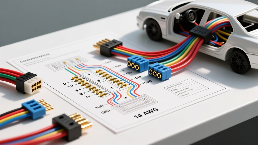
Introduction to the Stan's Auto Electrical Methodology
For master technicians and advanced DIYers, deciphering a complex vehicle wiring schematic is not merely about following lines on a page; it is about understanding the architectural flow of current, logic gates, and voltage thresholds. The Stan's Auto Electrical methodology has become an industry-respected framework for systematically walking through wiring diagrams, isolating faults, and verifying custom harness integrations. Unlike generic troubleshooting that relies on guesswork, this approach mandates a strict node-by-node verification process, bridging the gap between theoretical schematic design and real-world copper-and-pin reality.
In this complete wiring diagram walkthrough, we will apply the Stan's Auto Electrical principles to decode a primary starter and accessory circuit. We will cover wire gauge specifications, connector pinouts, relay logic, and the precise color-coding standards required to diagnose or build a reliable automotive electrical system.
Pre-Walkthrough: Schematics, Standards, and Diagnostic Tools
Before tracing a single circuit, the Stan's method requires verifying the baseline schematic against SAE J1128 standards for low-tension primary cables. Automotive environments subject wiring to extreme thermal cycling and vibration. A diagram might call for a 12 AWG wire, but if the routing passes near exhaust manifolds, the insulation jacket rating (e.g., Tefzel vs. Cross-linked Polyethylene) becomes just as critical as the copper cross-section.
Essential Diagnostic Equipment
- Digital Multimeter (DMM): A high-impedance DMM (minimum 10 Megohm input impedance) like the Fluke 88V to prevent loading sensitive ECM circuits during voltage drop tests.
- Power Probe: For safely applying fused 12V or ground to actuator circuits without back-probing and spreading connector terminals.
- Terminal Tension Gauges: To verify pin retention in Weather-Pack and Metri-Pack 280 connectors before final assembly.
Step-by-Step Diagram Walkthrough: The Primary Starter Circuit
Let us walk through a classic, high-amperage starter circuit utilizing a remote starter solenoid—a common setup in classic V8 restomods and heavy-duty trucks. The Stan's Auto Electrical method divides this into two distinct sub-circuits: the High-Amperage Feed (B+) and the Low-Amperage Control Logic.
Tracing the B+ and Ignition Switch Paths
Node 1: The Battery and Fusible Link
Current originates at the battery positive terminal. According to the schematic, a 4 AWG main feed travels to a fusible link block. The Stan's method dictates verifying the fusible link rating; for a standard passenger vehicle starter, a 175-Amp Mega Fuse or a 10 AWG fusible link (rated for roughly 60A continuous, but designed to protect the harness during a 400A+ stall current event) is standard.
Node 2: The Remote Solenoid (High Current)
The 4 AWG red cable terminates at the 'BATT' stud of the remote solenoid. A secondary 6 AWG red cable runs from the 'MOTOR' stud to the starter motor's S-terminal. When the solenoid engages, this bridge closes, delivering upwards of 250 amps to the starter.
Node 3: The Control Circuit (Low Current)
The activation of the solenoid relies on a standard ISO mini relay. Tracing the schematic:
- Pin 30 (Power In): Fused 12V constant from the ignition switch (14 AWG Pink wire).
- Pin 87 (Power Out): 14 AWG Yellow wire routed to the solenoid's 'S' (Start) terminal.
- Pin 86 (Coil Power): 16 AWG Pink/White stripe wire from the Neutral Safety Switch (NSS) or clutch interlock.
- Pin 85 (Coil Ground): 16 AWG Black wire terminating at a dedicated chassis ground star-point.
Decoding Custom Harness Color Codes and AWG Specifications
A critical component of the Stan's Auto Electrical walkthrough is cross-referencing the physical harness against the schematic's bill of materials. Custom harness builders often deviate from OEM factory colors, relying instead on standardized aftermarket performance color codes. Below is the reference chart used to verify wire sizing and function during a physical inspection.
| Circuit Function | Standard Wire Color | AWG Size | Max Amp Rating (Chassis) | Connector Type |
|---|---|---|---|---|
| Main Battery Feed (B+) | Red | 4 AWG | 120A - 150A | Ring Terminal (5/16") |
| Starter Solenoid Trigger | Yellow | 14 AWG | 15A - 20A | Weather-Pack 150 |
| Ignition Switched (Run) | Pink | 14 AWG | 15A - 20A | Metri-Pack 280 |
| Sensor Signal (e.g., TPS) | Light Green | 20 AWG | 3A - 5A | Deutsch DT Series |
| ECU / Chassis Ground | Black (or Black/White) | 10 AWG (Main) / 18 AWG (Signal) | 30A / 5A | Ring Terminal / Star Washer |
Note: Amp ratings are based on single conductor in free air at 50°C ambient, per Painless Performance Products wiring guidelines.
Troubleshooting Grounding and Relay Logic via Schematics
The most frequent failure mode identified during a Stan's Auto Electrical walkthrough is not a broken power wire, but a compromised ground path. Schematics often depict grounds as simple lines ending in a hash symbol (#). In reality, these represent physical termination points that are highly susceptible to corrosion, paint insulation, and vibration loosening.
Identifying Voltage Drop on Paper vs. Reality
When tracing a headlight circuit on a diagram, the power side shows 12V from the battery to the relay, through the switch, to the bulb. The ground side shows a path to the chassis. If the headlights are dim, a novice might assume a failing bulb or weak alternator. The Stan's method requires a live voltage drop test across the ground path.
- Set the DMM to DC Volts.
- Place the red probe on the battery negative terminal.
- Place the black probe on the headlight connector's ground pin.
- Turn the headlights on.
A reading greater than 0.10V (100mV) indicates excessive resistance in the ground circuit. If the schematic routes this ground through a splice pack (e.g., GM's G201 ground block), the walkthrough dictates inspecting the splice pack for green copper oxide corrosion, which acts as a semiconductor and creates erratic voltage drops under load.
Advanced Integration: Electric AC Compressor Clutch Circuits
Modern restorations and custom builds frequently integrate electric AC compressors. These units draw significant inrush current (often 30A to 40A) and require precise relay logic to prevent ECM damage. Applying the Stan's Auto Electrical walkthrough to an aftermarket Sanden-style electric compressor circuit reveals critical integration points.
The Logic Gate:
The compressor clutch relay coil (Pins 85/86) should not be triggered directly by the dashboard AC switch. The dashboard switch typically handles low current (under 5A). Instead, the schematic must show the dash switch triggering a low-current relay, which then feeds the high-current compressor clutch relay. Furthermore, a binary or trinary pressure switch must be wired in series on the ground side (Pin 85) of the clutch relay. This ensures that if refrigerant pressure drops below 35 PSI or spikes above 400 PSI, the ground path is severed, instantly de-energizing the clutch to prevent catastrophic compressor failure.
Wire Routing and EMI Suppression:
Because the compressor clutch is an inductive load, collapsing the magnetic field when the relay opens generates a massive voltage spike (back EMF). The walkthrough mandates the installation of a flyback diode across the relay coil (Pins 85 and 86), with the diode stripe facing the 12V source. Without this, the back EMF can exceed 100V, traveling back through the harness and frying sensitive EFI engine management modules. Reference materials like Haynes automotive electrical tutorials frequently emphasize the necessity of flyback diodes in custom EFI conversions.
Conclusion and Best Practices
Executing a complete wiring diagram walkthrough using the Stan's Auto Electrical method transforms an overwhelming web of copper into a logical, verifiable sequence of nodes. By strictly adhering to AWG specifications, verifying connector pin tension, and performing live voltage drop tests against the schematic's theoretical paths, technicians can eliminate parasitic draws, prevent harness fires, and ensure long-term electrical reliability. Always remember: a schematic is only a map; the physical verification of every splice, ground star-washer, and relay pin is the actual journey.