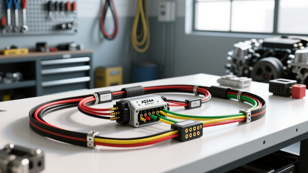
The Philosophy of ADV Auto Electrical Integration
When executing a modern engine swap or restoring a classic vehicle, relying on outdated, simplified wiring schemes leaves reliability and performance on the table. True ADV auto electrical (Advanced Auto Electrical) integration requires a fundamental understanding of ECU-controlled pulse-width modulation (PWM), precise voltage sensing, and high-current routing. This complete wiring diagram walkthrough dissects the critical starter and alternator circuits of a GM LS-platform engine swap, applying advanced architectural principles to ensure zero voltage drop and flawless ECU communication. By moving beyond the archaic 'one-wire' alternator setups, we can leverage the full diagnostic and efficiency capabilities of modern charging systems.
Starter Motor Circuit: High-Amperage Routing and Solenoid Logic
The starter circuit in an LS swap (typically utilizing a 1.4kW to 1.7kW PG260-LSA or Denso starter) demands meticulous attention to cable sizing and voltage drop mitigation. During cranking, the starter can draw in excess of 350 amps. If the cable gauge is insufficient, the resulting voltage drop will starve the ECU and fuel injectors of the minimum 9.0V required to maintain synchronization during crank.
Starter Cable Sizing Matrix
According to the SAE J1141 Standard for electrical cable sizing, wire length dictates the necessary American Wire Gauge (AWG) to maintain a voltage drop below 0.5V under peak load. Always measure the actual routed length, not the straight-line distance.
| Routed Cable Length | Minimum AWG (Copper) | Recommended Wire Type |
|---|---|---|
| Under 4 Feet | 4 AWG | SGX / Welding Cable |
| 4 to 7 Feet | 2 AWG | SGX / Welding Cable |
| 7 to 10 Feet | 1/0 AWG | SGX / Welding Cable |
| Over 10 Feet | 2/0 AWG | SGX / Welding Cable |
Solenoid Trigger Circuit and Relay Logic
Never route the ignition switch's 'Start' signal directly to the starter solenoid. The OEM GM starter solenoid requires a high-current pulse (up to 30 amps) to pull the plunger, followed by a lower hold current. To prevent voltage drop across the firewall and ignition switch contacts, implement a dedicated 30A Bosch-style relay.
- Pin 30 (Relay Input): Fused 10 AWG TXL wire directly from the battery distribution block.
- Pin 86 (Relay Coil Ground): 14 AWG TXL to a clean chassis ground.
- Pin 85 (Relay Coil Trigger): 14 AWG TXL from the ignition switch 'Start' position (Circuit 3).
- Pin 87 (Relay Output): 12 AWG TXL routed to the starter solenoid 'S' terminal spade.
Torque Spec: The starter B+ terminal nut must be torqued to exactly 10 Nm (89 lb-in) to prevent arcing under high-amperage draw.
AD244 Alternator 4-Pin Connector Walkthrough
The GM AD244 (145A) and AD230 (105A) alternators represent the gold standard for LS swaps. However, their advanced auto electrical capabilities are entirely dependent on the correct wiring of the 4-pin Metri-Pack 280 series connector (OEM Pigtail Part #15326836). Bypassing these pins to create a '1-wire' setup disables the ECU's ability to manage electrical load, leading to idle surge and premature battery degradation.
Pinout and Circuit Architecture
| Pin | Terminal Name | Wire Color (OEM) | AWG | Function & Routing Rules |
|---|---|---|---|---|
| A | L-Terminal (Lamp/Control) | Dark Blue / Gray | 18 AWG | Receives a 5V PWM signal from the ECU to dictate alternator field strength based on calculated electrical load. |
| B | F-Terminal (Field/Fault) | Red / White | 18 AWG | Outputs a 5V square wave back to the ECU and dash cluster to indicate alternator health and rotor field status. |
| C | S-Terminal (Sense) | Red | 12 AWG | Critical: Reads actual battery voltage. Must be fused (15A MAXI) at the battery and routed directly to the positive terminal. Do not connect to the alternator B+ post. |
| D | Shell Ground | N/A | N/A | Internal ground reference through the connector shell and alternator casing. |
The Sense Wire (Pin C) Imperative
The most common failure in ADV auto electrical LS swaps is misrouting the S-Terminal sense wire. If Pin C is jumpered to the alternator's B+ output post, the internal voltage regulator measures voltage at the alternator, not at the battery. Because a high-output audio system or electric cooling fans can cause a 0.8V drop between the alternator and the battery, the battery will chronically undercharge at 13.2V while the alternator believes it is outputting a perfect 14.0V. Always route the 12 AWG Red sense wire directly to the main battery positive stud or the primary chassis distribution block, protected by an inline 15-amp fuse.
Grounding Architecture: The Star-Point Topology
Advanced auto electrical systems are highly sensitive to ground plane noise. Daisy-chaining grounds (e.g., Alternator -> Block -> Chassis -> Battery) introduces variable resistance into the ECU's sensor return paths, causing erratic IAT (Intake Air Temperature) and TPS (Throttle Position Sensor) readings.
Executing a Proper Star Ground
- Engine Block to Chassis: Use a minimum 2 AWG braided copper ground strap. Attach from a clean, bare-metal location on the rear of the cylinder head to a dedicated, welded chassis stud. Torque the mounting bolt to 25 Nm.
- Alternator Case Ground: The AD244 relies on its mounting ears for secondary grounding. Ensure the aluminum bracket mounting surfaces are completely free of powder coat or anodizing. Use a die grinder to expose bare metal where the alternator ears mate to the bracket.
- ECU Ground Plane: The ECU black ground wires (Pins 1, 2, and 3 on the X2 connector) must be terminated at a single, dedicated star-point stud on the engine block, isolated from high-current starter return paths.
Termination Standards: Crimp vs. Solder
In high-vibration, high-heat engine bays, soldered wire connections are a liability. Solder wicks into the wire strands, creating a rigid stress point that will inevitably fatigue and snap. Aptiv (formerly Delphi) engineering standards dictate the use of precision gas-crimping for all Metri-Pack terminals.
- Tooling: Use a ratcheting crimp tool calibrated for Metri-Pack 150 and 280 series terminals (e.g., Delphi 12094430 or equivalent).
- Sealing: Always utilize dual-wall, adhesive-lined heat shrink (3M MDT or equivalent). The inner melamine adhesive melts and flows into the wire strands, creating a waterproof, anaerobic seal that prevents green-copper corrosion (verdigris) inside the terminal barrel.
- Cavity Plugs: Any unused pin cavity in a connector must be sealed with the appropriate silicone cavity plug (e.g., Metri-Pack 280 cavity plug #15305171) to prevent moisture ingress and terminal oxidation.
Troubleshooting Decision Tree: Charging System Faults
When diagnosing ADV auto electrical charging faults, avoid the trap of immediately replacing the alternator. Use this structured decision tree to isolate the root cause using a digital multimeter (DMM).
Symptom: Battery Voltage Reads 12.6V at Idle (Alternator Not Charging)
- Step 1: Verify B+ Output. Measure voltage at the alternator B+ post relative to the alternator case.
- If 13.8V - 14.4V: Alternator is charging. Proceed to Step 2.
- If 12.6V: Alternator is not energized. Proceed to Step 3.
- Step 2: Check Voltage Drop on Charge Cable. Place DMM positive lead on alternator B+ post, negative lead on battery positive post. Rev engine to 2000 RPM with headlights on.
- If DMM reads > 0.2V: High resistance in the charge cable or poor B+ terminal crimp. Replace 8 AWG charge wire.
- If DMM reads < 0.2V: Check the main battery negative ground strap for corrosion.
- Step 3: Verify L-Terminal (Pin A) PWM Signal. Back-probe Pin A with the engine running.
- If 0V: Open circuit between ECU and alternator. Check for broken 18 AWG Dark Blue wire.
- If steady 12V: ECU is commanding full charge, but alternator regulator has failed internally. Replace AD244 regulator or complete unit.
- Step 4: Verify S-Terminal (Pin C) Sense Voltage. Back-probe Pin C.
- If Pin C reads < 12.0V while Battery reads 12.6V: The sense wire is routed incorrectly or the inline 15A fuse is blown. The regulator is limiting output due to perceived over-voltage or open-sense fault.
Conclusion
Mastering advanced auto electrical principles transforms a frustrating engine swap into a reliable, factory-caliber installation. By adhering to SAE cable sizing standards, properly routing the AD244 sense and PWM circuits, and executing a flawless star-ground topology, you ensure that the vehicle's electrical architecture can handle the demands of modern fuel injection, electric cooling fans, and high-amperage accessories without voltage degradation. For further OEM wiring schematics and pinout matrices, consult Helm Incorporated GM Service Documentation to cross-reference your specific ECU calibration.