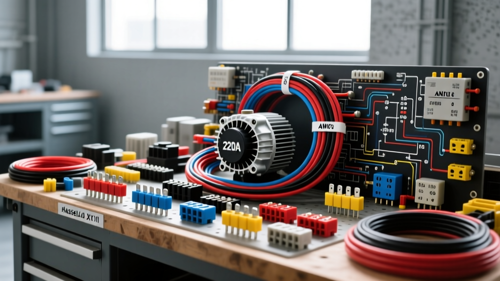
The Sergio's Auto Electric Benchmark for High-Amp Architectures
In the realm of custom automotive electrical systems, restomods, and high-draw off-road vehicles, the 'Sergio's Auto Electric' methodology has emerged as an industry-recognized benchmark for bulletproof charging and starting circuits. When vehicles are equipped with massive electric cooling fans, winches, high-power audio amplifiers, and electric power steering, the factory 80A to 120A alternator and 4-gauge wiring architecture will inevitably fail. The Sergio's Auto Electric protocol dictates a rigorous, no-compromise approach to upgrading to 220A+ alternators, utilizing Oxygen-Free Copper (OFC) cabling, military-spec crimping, and remote solenoid routing to eliminate voltage drop and heat soak.
This technical reference breaks down the exact specifications, wire color codes, AWG sizing, and pin configurations required to build a charging and starting system that meets the stringent Sergio's Auto Electric standards. Unlike basic one-wire alternator conversions that rely on internal sensing and suffer from dimming headlights at idle, this architecture mandates a fully optimized 3-wire Denso-style configuration with dedicated remote voltage sensing.
High-Output Alternator Routing Specifications
The foundation of the Sergio's Auto Electric charging system is the rejection of Copper Clad Aluminum (CCA) wire. All main power and ground runs must utilize 100% OFC stranded wire, meeting or exceeding SAE J1128 standards for low-tension primary cable with a 125°C temperature rating. The alternator B+ output is routed through a centralized ANL fuse block rather than a fusible link, ensuring rapid clearing in the event of a dead short while minimizing resistance.
Alternator Pinout and Wire Color Codes
- B+ (Battery Positive Output): 1/0 AWG Red OFC wire. This massive gauge is necessary to handle 220A continuous output with less than a 0.2V drop over a 6-foot run. Terminated with 3/8-inch hex-crimped ring terminals.
- Pin 1 (Remote Voltage Sense): 10 AWG Yellow wire. This wire must bypass the firewall and connect directly to the positive terminal of the starter battery or the positive bus bar. It provides the alternator's internal regulator with the true system voltage, compensating for any voltage drop across the main B+ cable.
- Pin 2 (Ignition / Exciter): 14 AWG Blue wire. Routed to a switched 12V ignition source. To protect the alternator's internal diodes from voltage spikes during engine shutdown, a 10A ATO inline fuse is mandated, followed by a 50-ohm ceramic resistor or a standard 194 wedge base warning bulb to provide the initial excitation current.
Table 1: High-Amp Charging System Component Specifications
| Circuit Component | Wire Gauge / Type | Terminal / Connector | Protection / Fuse | Torque Specification |
|---|---|---|---|---|
| Alternator B+ to Busbar | 1/0 AWG OFC (Red) | 3/8" Ring, Hex-Crimp, 3:1 Adhesive Heat Shrink | 250A ANL Fuse (Copper Element) | 12 Nm (8.8 lb-ft) |
| Busbar to Battery Positive | 1/0 AWG OFC (Red) | Military Spec Lead-Acid Clamp | None (Downstream of ANL) | 15 Nm (11 lb-ft) |
| Remote Sense (Pin 1) | 10 AWG OFC (Yellow) | 10-8 AWG Vinyl Insulated Fork | 20A Maxi-Fuse | 2.5 Nm (22 lb-in) |
| Ignition Exciter (Pin 2) | 14 AWG OFC (Blue) | 16-14 AWG Nylon Insulated Spade | 10A ATO Inline Fuse | N/A (Push-on) |
Starter Circuit & Ford Solenoid Relocation
A critical failure point in high-compression or high-heat engine bays is starter heat soak. As the exhaust headers radiate heat, the starter's internal solenoid resistance increases, leading to slow cranking and eventual solenoid welding. The Sergio's Auto Electric methodology solves this by relocating the primary high-amp switching to a remote, fender-mounted Ford-style continuous duty solenoid. This allows the heat-soaked starter solenoid to function solely as a mechanical engagement relay, while the heavy current draws through the remote solenoid mounted in a cool zone.
Starter Routing Architecture
The main battery positive is routed via 2 AWG OFC wire to the input stud of the remote solenoid. The output stud of the remote solenoid is then routed via 2 AWG OFC wire directly to the starter motor's main B+ terminal. The starter's own solenoid trigger wire (usually the 'S' terminal) is jumpered directly to the starter's main B+ terminal. When the remote solenoid engages, it sends 12V to the starter B+, which simultaneously powers the starter motor and triggers the local engagement solenoid, throwing the Bendix gear into the flexplate.
Table 2: Remote Solenoid Pinout and Control Circuit
| Solenoid Terminal | Function | Wire Gauge & Color | Routing Destination |
|---|---|---|---|
| Large Stud A (Input) | Main Battery Power In | 2 AWG Red OFC | Battery Positive Busbar |
| Large Stud B (Output) | Switched Power Out | 2 AWG Red OFC | Starter Motor Main B+ Terminal |
| Small 'S' Terminal | Pull-in Coil Trigger | 12 AWG Purple OFC | Ignition Switch 'Start' Position |
| Small 'I' Terminal | Ignition Bypass (Optional) | 14 AWG Pink OFC | Coil Positive (Points Ignition Only) |
Grounding Architecture: The Centralized Brass Bus
Grounding is where 90% of custom automotive electrical systems fail. The Sergio's Auto Electric protocol strictly forbids 'daisy-chaining' grounds or relying on the engine block to chassis rust for high-amp return paths. Instead, a centralized grounding architecture is employed using a solid brass or copper busbar mounted to the chassis in a dry, accessible location.
The engine block is tied to the chassis using a minimum of 2 AWG braided copper ground straps. Braided straps are mandated over insulated wire for engine-to-chassis connections because they withstand the high-frequency vibration and articulation of engine mounts without suffering from internal strand fatigue and breakage. The alternator case ground is validated by ensuring the mounting brackets are bare metal. If powder-coated brackets are used, a dedicated 10 AWG black ground wire must be run from the alternator case to the engine block to ensure the regulator has a true zero-volt reference.
Validation and Voltage Drop Testing
Following the physical installation, the system must be validated using voltage drop testing under load, a cornerstone of professional diagnostics championed by resources like Mad Electrical. A digital multimeter is set to DC Volts.
- B+ Cable Drop Test: Place the red probe on the alternator B+ terminal and the black probe on the battery positive terminal. Start the engine and turn on all electrical loads (headlights, blower motor on high, cooling fans). The multimeter should read less than 0.2V. A reading of 0.5V or higher indicates a poor crimp, undersized wire, or a failing ANL fuse element.
- Ground Circuit Drop Test: Place the red probe on the alternator case and the black probe on the battery negative terminal. Under the same heavy load conditions, the reading must be below 0.1V. Higher readings indicate inadequate engine-to-chassis grounding or painted mounting surfaces.
- Sense Wire Verification: Measure the voltage at the battery terminals, then measure at the alternator's Pin 1 (Sense). The two readings should be identical (within 0.05V). If the sense wire reads higher than the battery, the wire is routed incorrectly or is picking up induced AC noise from spark plug wires.
Troubleshooting the Sergio's Auto Electric Setup
Even with meticulous adherence to these specifications, environmental factors can introduce faults. Below is a decision tree for common anomalies in high-amp custom charging systems.
- Symptom: Alternator whines through the audio system, and headlights pulse at idle.
Cause: The 1/0 AWG B+ cable is routed parallel to the RCA cables or the sense wire is picking up alternator ripple current.
Fix: Reroute the 10 AWG Yellow sense wire away from high-current B+ cables. Ensure the audio system's main ground is tied to the same centralized brass busbar as the alternator ground to establish a common reference point. - Symptom: Starter clicks once, but does not crank the engine; battery shows 12.6V.
Cause: Voltage drop across the remote Ford solenoid contacts due to internal pitting, or excessive resistance in the 2 AWG starter cable.
Fix: Perform a voltage drop test across the two large studs of the remote solenoid while the key is held in the 'Start' position. If the drop exceeds 0.5V, replace the solenoid. Verify that the 2 AWG lugs were hex-crimped; indent crimps often loosen under the high thermal cycling of starter loads. - Symptom: System voltage sits at 13.2V instead of the expected 14.4V under load.
Cause: The remote sense wire (Pin 1) has lost continuity, forcing the alternator to default to internal sensing, which reads the lower voltage present at the alternator's rear housing.
Fix: Check the 20A Maxi-Fuse on the yellow sense wire circuit. Inspect the firewall grommet pass-through for pinched insulation.
By adhering strictly to these wire gauges, crimping methodologies, and routing protocols, builders can achieve a resilient, high-output electrical architecture capable of supporting the most demanding modern accessories in classic and custom vehicle platforms. For further reading on custom harness routing and high-amp alternator integration, consult the technical bulletins provided by Painless Performance Products and relevant SAE automotive electrical standards.