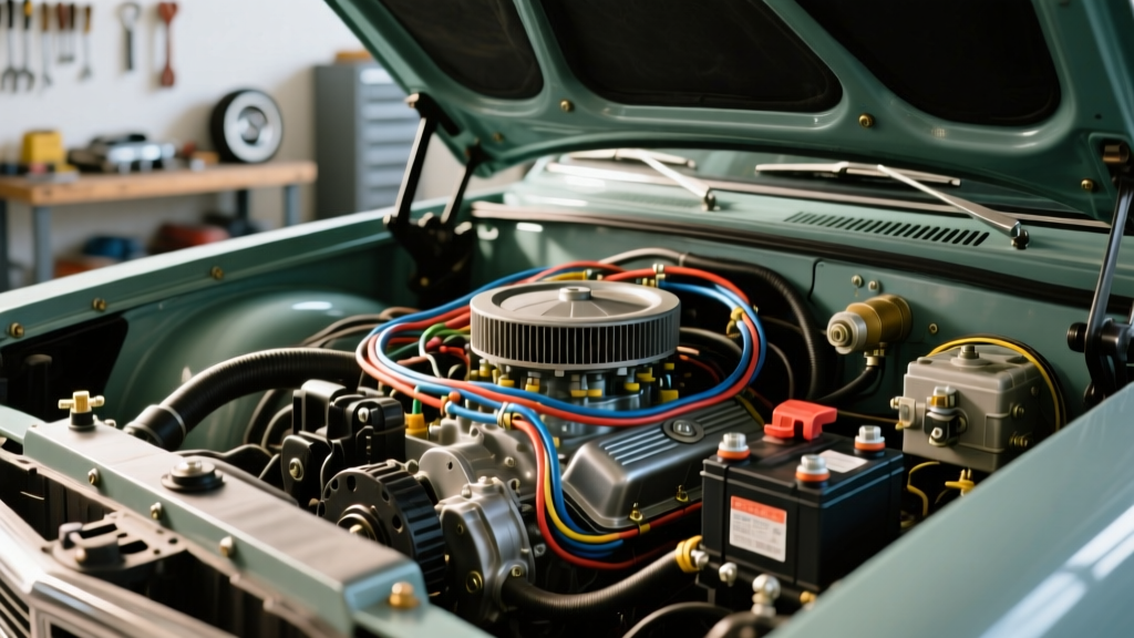
Project Overview: Beating the Southern Heat
When executing a high-draw LS-swap into a classic 1972 C10 chassis, the factory 63-amp internally regulated SI-series alternator is woefully inadequate. Modern electric fuel pumps, EFI controllers, and electric AC compressors demand a minimum of 140 amps at idle. This upgrade guide is based on a recent heavy-duty modification project where we collaborated with an auto electric Tupelo MS specialist to address the unique challenges of extreme Southern heat, high humidity, and massive parasitic electrical loads. Under-hood temperatures in Mississippi summers routinely exceed 210°F near the exhaust manifolds, which rapidly degrades standard PVC wire insulation and causes severe voltage drop.
Climate-Resilient Wiring Selection
To combat thermal degradation, this project exclusively uses SAE J1128 compliant cross-linked polyethylene (XLPE) insulated wire. Specifically, we selected SXL (Thick Wall) and GXL (Thin Wall) X-Link marine-grade cables. According to the SAE J1128 Low Tension Primary Cable Standard, XLPE insulation maintains dielectric integrity up to 125°C (257°F), compared to the 105°C limit of standard TWP (Thermoplastic) wire. For the main charge circuit, 1/0 AWG X-Link cable is mandatory to handle the 220-amp peak output of our upgraded AD244 alternator without inducing resistance-based heat.
AD244 High-Amp Alternator Pinout & Integration
The Delco Remy AD244 is a 4-pin, internally regulated alternator capable of 145+ amps at idle and 220 amps at highway RPMs. Proper integration with the vehicle's ignition and EFI system requires precise pinout wiring. Below is the definitive wiring specification for the AD244 4-pin connector.
| Pin | Function | Wire Gauge | Wire Color | Circuit Description |
|---|---|---|---|---|
| 1 | L (Lamp) | 14 AWG | Brown | Dash warning lamp / PCM wake-up signal |
| 2 | F (Field) | 12 AWG | Gray | Field duty cycle PWM signal to PCM |
| 3 | S (Sense) | 10 AWG | Red | Direct battery voltage sense (Critical) |
| 4 | I (Ignition) | 14 AWG | Pink | Switched 12V ignition excitation source |
Pin Circuit Deep-Dive
- Pin 1 (L - Lamp): Connects to the dash warning lamp and provides the initial wake-up signal to the internal regulator. A 10-ohm, 1/2-watt resistor must be placed in parallel if an LED dash bulb is used to ensure adequate current draw for regulator turn-on.
- Pin 2 (F - Field): Outputs a 5V PWM (Pulse Width Modulation) duty cycle signal to the PCM, allowing the engine computer to monitor alternator load and adjust idle air control (IAC) to prevent stalling during high-load electrical spikes.
- Pin 3 (S - Sense): This is the most critical circuit. It must be routed directly to the positive battery terminal or the main distribution block. If wired to the alternator B+ post, the regulator will sense charging voltage at the alternator, not the battery, resulting in chronic undercharging.
- Pin 4 (I - Ignition): Connects to a switched 12V ignition source. This circuit provides secondary excitation to the regulator.
Installation Note: When bolting the AD244 to the LS cylinder head bracket, the M8 mounting bolts must be torqued to exactly 22 Nm (16 lb-ft) to prevent case warping while ensuring adequate chassis grounding.
1/0 AWG Charge Cable Routing & Crimping
The physical routing of the 1/0 AWG main charge cable is where most modification projects fail. The cable must maintain a minimum 6-inch clearance from LS exhaust headers. We routed the positive cable along the inner fender well, securing it every 12 inches with stainless steel Adel clamps lined with high-temperature silicone.
For terminating the 1/0 AWG cable, we use pure copper 3/8-inch ring terminals. Never use open-barrel crimps or solder-only connections for high-amp circuits; solder can wick into the wire strands, creating a rigid stress point that fractures under engine vibration. Instead, use a dedicated hex-crimp die tool. A hex crimp compresses the copper terminal evenly around the wire strands, maximizing surface contact area and minimizing electrical resistance. After crimping, seal the termination with 3M adhesive-lined dual-wall heat shrink. The inner adhesive layer melts and flows into the wire strands, creating a waterproof, oxygen-free seal that prevents green copper corrosion.
Dual Battery Smart Isolator Integration
For overlanding and heavy auxiliary loads, a secondary battery is required. We installed a Hellroaring BIC-95150 Battery Isolator/Controller. Unlike old-school diode-based isolators that introduce a 0.6V forward voltage drop, the Hellroaring unit uses heavy-duty MOSFETs to bridge the primary and secondary batteries with near-zero resistance. The main 1/0 AWG charge wire from the alternator feeds the primary stud, while a secondary 1/0 AWG X-Link cable routes to the auxiliary battery in the bed. The control module monitors the primary battery voltage; when it exceeds 13.1V for 30 seconds, the MOSFET bridge closes, charging the secondary battery. If the primary voltage drops below 12.7V, the bridge opens, ensuring the starting battery is never depleted by auxiliary loads like a 12V fridge or winch.
Electric AC Compressor Relay Integration
Upgrading to a modern Sanden SD7 electric-style clutch compressor requires a robust relay circuit to handle the initial inrush current of the clutch coil, which can spike to 25 amps before settling at a steady 3.5 amps. We utilize a Hella 4RA 003 510-001 Bosch-style 5-pin relay to isolate the high-current load from the delicate Vintage Air thermostat switch. Referencing the Hella Automotive Relay Technical Guide, we ensure the relay's internal contactor is rated for the specific inductive load of the AC clutch.
| Relay Pin | Function | Wire Gauge | Routing Destination |
|---|---|---|---|
| 30 | 12V+ Input | 8 AWG | AD244 B+ terminal via 30A Maxi fuse |
| 87 | NO Output | 10 AWG | AC compressor clutch coil positive |
| 85 | Ground | 14 AWG | Clean firewall ground stud (star washer) |
| 86 | Trigger Input | 16 AWG | Vintage Air thermostat request signal |
| 87a | NC Output | N/A | Unconnected and insulated |
Voltage Drop Testing & Final Verification
A wiring upgrade is incomplete without rigorous voltage drop testing. According to Painless Performance Wiring Technical Manuals, a healthy 12V charging circuit should exhibit no more than a 0.2V drop across the positive cable and 0.1V across the ground path under maximum load.
To test, set your digital multimeter to DC Volts. Connect the red probe to the alternator B+ post and the black probe to the positive battery terminal. Start the engine, turn on the electric cooling fans, headlights, and AC compressor to simulate maximum load. If the multimeter reads greater than 0.5V, you have excessive resistance in the 1/0 AWG cable, a poor crimp, or a corroded terminal. Repeat the test on the ground side by probing the alternator case and the negative battery terminal.
This meticulous approach to wire selection, termination, and load testing ensures your classic truck's electrical system will reliably support modern EFI and AC demands, regardless of the brutal Southern summer climate.