The Santiago Auto Electric Methodology: A Beginner's Foundation
When approaching automotive electrical systems, beginners often feel overwhelmed by the sheer volume of wiring hidden beneath dashboards and within engine bays. The Santiago Auto Electric methodology strips away the confusion by focusing on systematic circuit isolation, strict adherence to SAE (Society of Automotive Engineers) standards, and an unwavering reliance on voltage drop testing rather than simple continuity checks. Whether you are repairing a daily driver or building a custom harness, understanding the fundamental architecture of a 12-volt DC system is mandatory. This guide breaks down the core principles of vehicle electrical design, from high-current starter circuits to low-amperage relay control networks, providing you with the exact specifications needed to wire, diagnose, and repair automotive systems safely and effectively.
Core High-Current Architecture: Starter and Alternator Circuits
The highest current demands in any standard internal combustion vehicle come from the starter motor and the alternator. Misunderstanding the wire gauges or pin configurations for these components is the leading cause of electrical fires and chronic undercharging issues.
Starter Motor and Solenoid Wiring
The starter circuit is divided into two distinct paths: the high-current motor feed and the low-current solenoid trigger. The main battery positive (B+) cable connects directly to the starter's B+ terminal. For most passenger vehicles and light trucks, this requires a 1/0 AWG or 2 AWG stranded copper cable with a heavy-duty ring terminal, torqued to the manufacturer's specification (typically 10-12 Nm for an M8 stud). The solenoid trigger wire connects to the 'S' terminal. This circuit only carries about 10 to 15 amps momentarily. According to AutoShop 101 electrical fundamentals, a 12 AWG TXL (Thin Wall Cross-Linked) wire is standard for the S-terminal. In many Asian and European platforms, this wire is color-coded Yellow with a Red tracer (Y/R), while GM platforms historically use a solid Purple wire. The S-terminal receives switched 12V from the ignition switch, often routed through a neutral safety switch or clutch interlock relay.
Alternator Output and Regulator Pinouts
Modern alternators utilize internal voltage regulators that require specific feedback loops to maintain a steady 13.8V to 14.4V system output. A common configuration is the Bosch-style or Denso SC-series 2-pin connector. Pin L (Indicator/Lamp) provides the initial field excitation current from the ignition switch via a dashboard warning lamp or a resistor wire. Pin S (Sense) is the critical feedback loop. The Sense wire must be routed directly to the main battery positive post or the primary distribution block to read the true system voltage. If the Sense wire is damaged or routed poorly, the alternator will overcompensate for phantom voltage drops, leading to battery overcharging and electrolyte boiling.
Understanding Relays: The ISO Mini Standard
Relays allow a low-current switch (like a dashboard button or an ECU transistor) to control a high-current load (like fuel pumps, cooling fans, or headlights) without melting the switch contacts. The global automotive standard for this is the ISO 7588-2 Mini Relay, commonly referred to as a standard 5-pin ISO relay.
ISO Relay Pin Configuration and DIN Color Codes
Understanding the pinout and the corresponding DIN 72552 terminal designations is critical for proper circuit design and troubleshooting. The coil resistance of a standard 12V ISO relay is typically between 70 and 90 ohms, drawing roughly 150mA of current.
| Pin Number | DIN Terminal | Function | Standard Wire Color (Control/Load) |
|---|---|---|---|
| 30 | 30 (Common) | Main Power Input (B+) | Red (Constant 12V) |
| 87 | 87 (NO) | Normally Open Output (To Load) | Varies by Load (e.g., Blue for Headlights) |
| 87a | 87a (NC) | Normally Closed Output | Rarely used in standard auto applications |
| 85 | 31 (Ground) | Coil Ground | Black or Brown |
| 86 | 15 (Switched) | Coil Power (Switch/ECU Signal) | White or Green (Switched 12V) |
Note: Pins 85 and 86 control the electromagnetic coil. While they are generally non-polarized in standard relays, if your relay contains an internal suppression diode to protect solid-state ECU drivers, polarity matters immensely. Pin 86 must be B+ and Pin 85 must be Ground.
Wire Gauge (AWG) Selection and Voltage Drop
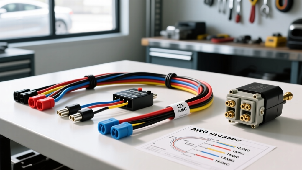
One of the most severe mistakes beginners make is sizing wire solely based on amperage capacity while ignoring circuit length. The Santiago Auto Electric approach strictly adheres to SAE J1128 standards for low-tension primary cable, which dictates that wire gauge must be selected to prevent a voltage drop exceeding 0.5 volts on high-current circuits and 0.2 volts on sensitive sensor circuits over the entire length of the wire (positive and ground combined).
AWG vs. Amperage and Voltage Drop Chart
The following chart assumes a standard 12V system, TXL insulation, and a maximum allowable voltage drop of 0.5V for the specified lengths.
| AWG Size | Max Continuous Amps | Max Length for 10A (ft) | Max Length for 20A (ft) | Typical Automotive Application |
|---|---|---|---|---|
| 18 AWG | 10A | 12 ft | N/A | ECU sensors, dashboard LEDs, low-draw relays |
| 14 AWG | 15A | 15 ft | 7 ft | Cigarette lighter sockets, interior lighting |
| 12 AWG | 20A | 18 ft | 9 ft | Fuel pumps, power windows, horn circuits |
| 10 AWG | 30A | 20 ft | 10 ft | High-amperage cooling fans, main headlight feeds |
| 4 AWG | 60A+ | N/A | N/A | Alternator B+ output, inverter feeds |
Fuse Technologies and SAE Standards
Fuses are sacrificial devices designed to protect the wiring harness, not the component. According to SAE J554 Electric Fuses standards, a fuse must be rated at approximately 125% of the continuous circuit load. The most common fuse types include the ATO/ATC (standard blade), Mini, and Maxi fuses for circuits up to 80 amps. For high-current primary distribution (such as the main battery feed to the fuse box), OEMs utilize Mega or AMG fuses (100A to 250A) and slow-blow MIDI fuses. These high-amperage fuses feature a specific time-current characteristic curve that allows them to absorb the massive, multi-second inrush current of a starter motor or a locked-rotor cooling fan without blowing prematurely.
Beginner Diagnostic Decision Tree: No-Crank Conditions
When a vehicle exhibits a 'no-crank' condition, beginners often immediately replace the starter motor. The Santiago Auto Electric methodology requires a systematic voltage drop test to isolate the exact point of failure. Follow this decision tree using a digital multimeter (DMM) set to DC Volts.
Step-by-Step Isolation Protocol
- Verify Battery State of Charge: Measure resting voltage at the battery posts. It must read a minimum of 12.4V. If below 12.2V, charge the battery before proceeding. A weak battery will skew all subsequent voltage drop tests.
- Test the Positive Feed (B+ Voltage Drop): Connect the DMM's red lead to the battery positive post and the black lead to the starter B+ terminal stud. Have an assistant crank the engine. The DMM should read less than 0.2V. If it reads higher, the battery cable is corroded, undersized, or the terminal connections are loose.
- Test the Ground Circuit (Ground Voltage Drop): Connect the DMM's black lead to the battery negative post and the red lead to a clean, unpainted metal surface on the starter motor casing. Crank the engine. The reading must be less than 0.1V. A higher reading indicates a faulty engine-to-chassis ground strap or poor battery negative terminal connection.
- Test the Solenoid Trigger (S-Terminal Signal): Back-probe the S-terminal wire at the starter connector. Connect the DMM red lead to the S-terminal wire and the black lead to the battery negative post. Turn the key to the 'Start' position. You must see at least 10.5V.
- If you see 0V: The fault is upstream (ignition switch, neutral safety switch, or starter relay).
- If you see 10.5V+ but the starter does not engage: The starter solenoid or motor is internally faulty. Replace the starter assembly.
Conclusion
Mastering automotive electrical systems does not require memorizing every wire in a 50-page factory service manual. It requires a deep understanding of the fundamental laws of DC electricity, strict adherence to wire gauge and voltage drop specifications, and a logical, step-by-step diagnostic approach. By applying these Santiago Auto Electric fundamentals, you can confidently design robust custom circuits, accurately diagnose complex parasitic draws, and ensure the long-term reliability of any vehicle's electrical architecture.