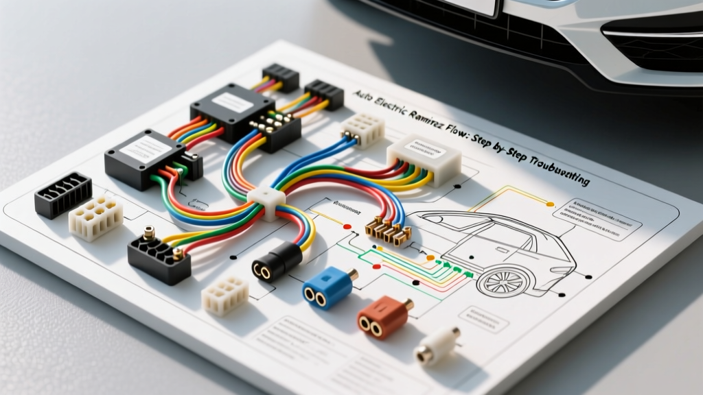
Introduction to the Ramirez Diagnostic Methodology
In the realm of advanced automotive electrical diagnostics, the 'Auto Electric Ramirez Flow' represents a highly structured, step-by-step troubleshooting methodology designed to eliminate the common pitfall of 'parts swapping.' Unlike basic continuity testing, which often yields false positives due to the inability of a standard digital multimeter (DMM) to measure resistance under load, the Ramirez protocol emphasizes dynamic circuit analysis, voltage drop thresholds, and oscilloscope verification. This guide breaks down the core tenets of this step-by-step troubleshooting flow, providing actionable wire color codes, AWG specifications, and pinout configurations for modern vehicle electrical architectures.
Whether you are diagnosing a parasitic draw on a late-model CAN-bus network or tracing a high-resistance fault in a high-current starter circuit, adhering to this systematic flow ensures accurate component isolation before any part is condemned.
Phase 1: Baseline Power and Ground Verification
The first step in the Ramirez troubleshooting flow is establishing a verified baseline. Modern Powertrain Control Modules (PCMs) and Body Control Modules (BCMs) require stable voltage to maintain internal logic states and injector pulse-width calculations. A cranking voltage drop below 9.6V will often cause the PCM to reset, resulting in a 'crank-no-start' condition that mimics a failed crankshaft position sensor.
Step 1.1: Battery State of Charge (SOC) and Surface Charge
Before connecting any diagnostic scan tool or DMM, measure the resting battery voltage. A fully charged lead-acid AGM battery should read between 12.66V and 12.80V at 70°F. If the vehicle has been sitting, remove the surface charge by turning on the high-beam headlights for 60 seconds.
Step 1.2: Alternator AC Ripple Testing
Diode trio failures in the alternator introduce alternating current (AC) ripple into the DC electrical system, which scrambles PCM sensor data. Set your DMM to AC Volts and probe the B+ terminal (typically a 10 AWG or 8 AWG red wire with a ring terminal) and the alternator case ground. Acceptable AC ripple is strictly less than 50mV (0.050V). Readings above 100mV indicate a failed rectifier bridge, requiring alternator replacement before proceeding with any sensor diagnostics.
Phase 2: The Voltage Drop Decision Tree
The core of the Ramirez method is the dynamic voltage drop test. A single strand of 22 AWG wire can pass a standard continuity test (showing 0.1 ohms) but will completely fail to carry the 15 amps required by a cooling fan motor. By measuring voltage drop while the circuit is under load, you identify high-resistance faults invisible to an ohmmeter.
Step-by-Step Voltage Drop Execution
- Configure the DMM: Set to DC Volts (Auto-ranging).
- Positive Side Test: Place the red probe on the battery B+ post and the black probe on the component's power input pin (e.g., Pin 87 of an ISO mini relay or the power feed pin of a Delphi Weather-Pack connector).
- Negative Side Test: Place the red probe on the component's ground output pin and the black probe on the battery negative post.
- Activate the Circuit: Command the component ON via a bi-directional scan tool or by manually jumping the relay control pins (85 and 86).
Ramirez Voltage Drop Tolerance Table
| Circuit Component | Wire Gauge (AWG) | Max Allowable Voltage Drop | Common Failure Mode |
|---|---|---|---|
| Battery Cable (B+ to Starter) | 4 AWG to 2/0 AWG | 0.20V | Corroded side-post terminal, loose torque (Spec: 120 in-lbs) |
| Engine Block Ground Strap | 6 AWG to 4 AWG | 0.10V | Paint/dielectric grease under ring terminal at chassis ground G102 |
| Standard ISO Relay Contacts | N/A (Internal) | 0.15V | Carbon pitting on Pins 30 and 87 internal contacts |
| Standard Blade Fuse (ATO) | N/A | 0.05V | Micro-fracture in fusible element or corroded fuse box bus bar |
| PCM Sensor Ground Wire | 18 AWG to 20 AWG | 0.05V | Splice corrosion in harness near firewall breakout |
Phase 3: 5-Volt Reference and CAN Bus Isolation
When baseline power and grounds are verified, the Ramirez flow moves to low-voltage signal circuits. Modern vehicles utilize a shared 5-Volt Reference (VREF) bus to power multiple analog sensors (MAP, TPS, EGR valve position, AC pressure transducer). A short-to-ground on any single sensor will pull the entire 5V bus down to 0V, disabling the fuel injection sequence.
Step 3.1: Isolating the 5V VREF Short
Do not immediately replace the PCM. Instead, follow this isolation sequence:
- Locate the PCM breakout connector (often a 160-pin or 38-pin TE Connectivity AMP Superseal harness connector).
- Identify the VREF supply pin (e.g., Pin 29 on many Ford 16W/20W harnesses, typically a Brown/White wire).
- With the key ON, engine OFF (KOEO), back-probe the VREF wire using a T-pin and measure voltage. If it reads 0.5V to 2.5V instead of 5.0V, a short is present.
- The Drop-Off Method: Systematically unplug sensors sharing the VREF circuit one by one. When the 5V reference instantly snaps back to 5.00V upon unplugging a specific sensor (like the AC pressure transducer on a Metri-Pack 150 connector), you have isolated the faulty component or its specific pigtail.
Step 3.2: High-Speed CAN Bus Diagnostics
Communication U-codes (e.g., U0100 Lost Communication with ECM) require CAN bus physical layer testing. Access the OBD-II Data Link Connector (DLC). According to SAE J1939 and ISO 15765-4 standards, the high-speed CAN bus operates on specific pins.
- Pin 6 (CAN-High): Typically White or White/Green wire. Idle voltage: ~2.6V.
- Pin 14 (CAN-Low): Typically White/Blue or White/Red wire. Idle voltage: ~2.4V.
- Pins 4 & 5 (Chassis/Signal Ground): Must have less than 0.05V drop to battery negative.
- Pin 16 (Battery Positive): Constant 12V, fused.
Terminating Resistor Test: Turn the ignition OFF. Set your DMM to Ohms. Measure resistance between DLC Pin 6 and Pin 14. You must read exactly 60 ohms. This confirms that the two 120-ohm terminating resistors (usually located inside the PCM and the Transmission Control Module) are present and the CAN bus wiring is intact. A reading of 120 ohms indicates an open circuit in the CAN bus backbone; a reading of 0 ohms indicates a dead short between CAN-H and CAN-L.
For advanced waveform analysis, technicians refer to the PicoScope Waveform Library to compare captured CAN-H and CAN-L differential signals against known-good patterns, looking for voltage spikes that indicate electromagnetic interference (EMI) from failing ignition coils or improper spark plug wire routing.
Phase 4: Actuator Ground Path and PWM Verification
The final phase of the Ramirez flow addresses Pulse Width Modulated (PWM) ground-side drivers. The PCM rarely supplies 12V directly to high-draw actuators like fuel injectors or EVAP purge solenoids. Instead, it switches the ground path using internal transistors.
When diagnosing a circuit where the actuator has verified B+ (12V) but is not operating, you must verify the PCM's PWM ground signal. Connect an oscilloscope or a logic probe to the control wire (often a 20 AWG wire, color-coded Yellow/Violet or similar depending on the manufacturer). During cranking or actuation, the scope should display a square wave toggling between 0V (transistor ON, completing the ground) and 12V-14V (transistor OFF, inducing flyback voltage).
If the square wave is present but the actuator remains dead, the fault lies in the actuator's internal coil (open circuit). If the signal stays at a flat 12V, the PCM driver is not triggering, pointing to a missing PCM enable condition (such as a failed ASD relay or a missing crankshaft synchronization signal). Always consult iATN (International Automotive Technicians Network) archives for manufacturer-specific pinout variations and known harness chafe points before condemning the PCM.
Summary of the Ramirez Troubleshooting Flow
The Auto Electric Ramirez methodology is built on the principle of absolute verification. By systematically moving from high-current baseline tests to dynamic voltage drop measurements, and finally to low-voltage network and PWM signal analysis, technicians can accurately map the electrical fault. Never rely on continuity alone; always test circuits under load, respect the strict voltage drop tolerances, and utilize differential measurements for network communication faults. This disciplined, step-by-step approach is the hallmark of elite automotive electrical diagnostics.