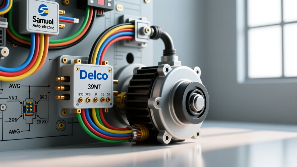
Introduction to Samuel Auto Electric Component Architectures
When sourcing, installing, or servicing heavy-duty commercial electrical components through Samuel Auto Electric, fleet technicians and master diagnosticians must adhere to strict wiring protocols. Samuel Auto Electric specializes in high-output alternators and gear-reduction starters—frequently based on robust Delco Remy 39MT/42MT starter and 28SI/34SI alternator architectures—designed for SAE Class 8 trucks, agricultural machinery, and marine applications. Improper wire sizing, inadequate crimping, or incorrect terminal routing on these high-amperage units inevitably leads to catastrophic solenoid welding, severe voltage drop, and premature brushless stator failure.
This technical specification reference outlines the exact AWG requirements, terminal pinouts, torque values, and diagnostic protocols required to maintain peak efficiency in Samuel Auto Electric heavy-duty starting and charging systems. All specifications align with SAE International standards, specifically SAE J1128 for Battery Cable Standards and SAE J541 for Starter Switch Circuits.
Heavy-Duty Starter Circuit Specifications (39MT/42MT Platforms)
Heavy-duty gear-reduction starters supplied by Samuel Auto Electric typically feature a four-terminal solenoid cap designed to manage immense inrush currents, which can exceed 1,200 amps during the initial lock-rotor phase of cranking. The solenoid utilizes a dual-coil system: a high-current pull-in coil and a low-current hold-in coil. Understanding the specific wiring requirements for each terminal is critical to prevent contactor bounce and terminal arcing.
Starter Terminal Pinout and Wire Sizing Matrix
| Terminal ID | Function | Required Wire Gauge (AWG / mm²) | Connector Type & Insulation | Max Continuous / Surge Current |
|---|---|---|---|---|
| B+ (BAT) | Main Battery Positive Input | 1/0 AWG (53.5 mm²) up to 6ft; 2/0 AWG over 6ft | Heavy-duty copper lug, 3:1 adhesive heat shrink | 1,200A Surge / 600A Cont. |
| S (Start) | Solenoid Pull-In Activation | 12 AWG (4.0 mm²) minimum; 10 AWG preferred | Sealed spade or ring terminal, vinyl insulated | 45A Surge (Pull-In Phase) |
| R (Relay) | Ignition Coil Bypass (Optional) | 14 AWG (2.0 mm²) | Sealed spade terminal | 15A Continuous |
| I (Ignition) | Solenoid Hold-In / ECM Logic | 14 AWG (2.0 mm²) | Sealed spade terminal | 3A Continuous (Hold-In Phase) |
Solenoid Pull-In vs. Hold-In Current Management
A common failure mode in Samuel Auto Electric starter installations involves undersizing the 'S' terminal wire. The pull-in coil requires a massive momentary surge (up to 45 amps) to physically close the heavy copper contactor disc against the B+ and Motor terminals. If a technician uses standard 16 AWG wire, the inherent resistance of the wire causes a voltage drop at the solenoid. This results in a slow, 'mushy' engagement. The contactor closes too slowly, causing sustained high-amperage arcing that welds the copper disc to the terminal studs, resulting in a starter that continues to spin even after the key is released. Always use a minimum of 12 AWG (preferably 10 AWG) for the S-terminal switch wire, routed through a heavy-duty 150A continuous-rated starter relay.
High-Output Alternator Wiring and Remote Sense Routing
Modern Samuel Auto Electric alternators, such as the 28SI and 34SI brushless platforms, are capable of producing upwards of 300 amps at engine idle. However, generating this amperage is useless if the vehicle's wiring harness cannot support the thermal and electrical load. Furthermore, brushless alternators rely heavily on accurate voltage sensing to regulate the rotor field current.
Alternator Terminal Specifications and Routing
| Terminal ID | Circuit Function | Wire Gauge & Routing Rules | Fusing Requirements |
|---|---|---|---|
| B+ (Output) | Main DC Output to Battery Bank | 1/0 AWG (53.5 mm²) stranded copper. Must route away from exhaust manifolds. | Mega Fuse (300A-400A) within 18 inches of battery post. |
| R (Remote Sense) | Regulator Voltage Feedback | 10 AWG (5.0 mm²). MUST connect directly to the positive battery post. | Inline blade fuse (5A) located near the battery connection. |
| I (Ignition) | Regulator Wake-Up / Field Flash | 14 AWG (2.0 mm²). Switched ignition source (12V in RUN/CRANK). | Inline fuse (10A). |
| L (Lamp) | Dashboard Charge Indicator | 18 AWG (0.8 mm²). Connects to OEM instrument cluster LED/Bulb. | Fused via OEM instrument cluster circuit. |
Mitigating Parasitic Voltage Drop via Remote Sense
The 'R' (Remote Sense) terminal is the most frequently miswired circuit on heavy-duty alternators. The internal voltage regulator uses the R-terminal to read the actual voltage at the battery bank. If a technician mistakenly jumps the R-terminal to the B+ terminal on the back of the alternator, the regulator will only measure voltage at the alternator output stud. Because a 300-amp load across 15 feet of battery cable will naturally induce a 0.5V to 1.0V drop, the alternator will undercharge the batteries, leading to chronic sulfation and premature battery death. The R-terminal wire must be an independent 10 AWG circuit run all the way back to the positive battery post, completely bypassing the high-current B+ cable path.
Mechanical Torque and SAE Crimping Standards
Electrical conductivity is only as reliable as the mechanical compression of the terminal. Samuel Auto Electric components utilize high-grade copper and brass terminal studs that are highly susceptible to stripping or thermal loosening if improper torque is applied. Furthermore, crimping heavy-gauge battery cables requires specialized tooling to achieve the necessary cold-weld compression ratio.
Fastener Torque Specifications
| Component / Stud Size | Thread Pitch | Required Torque (Nm) | Required Torque (lb-in / lb-ft) | Hardware Notes |
|---|---|---|---|---|
| Starter B+ Terminal | M10 x 1.5 | 12 - 15 Nm | 106 - 132 lb-in | Use serrated flange nut; do not use lock washers. |
| Alternator B+ Output | M8 x 1.25 | 9 - 12 Nm | 80 - 106 lb-in | Ensure insulator boot is seated before torquing. |
| Starter Mounting Bolts | M12 x 1.75 | 135 - 150 Nm | 100 - 110 lb-ft | Apply medium threadlocker (Loctite 243). |
SAE J1128 Compliant Crimping Protocols
For 1/0 AWG and 2/0 AWG battery cables, standard mechanical crimpers are insufficient. Technicians must use hydraulic or pneumatic hex-crimp dies (such as Burndy or AMP certified tooling) that compress the copper barrel into a hexagonal profile. This specific profile ensures maximum surface area contact and eliminates internal air pockets where moisture could ingress and cause galvanic corrosion. Following the crimp, the termination must be sealed using 3:1 shrink-ratio, dual-wall polyolefin heat shrink tubing with an inner layer of meltable adhesive. This adhesive flows into the wire strands during heating, creating a completely waterproof environmental seal that prevents the 'green rot' (copper oxide formation) that plagues poorly sealed heavy-duty harnesses.
Diagnostic Voltage Drop Testing Protocol
When a Samuel Auto Electric starter exhibits slow cranking or an alternator fails to reach peak output, technicians must abandon resistance testing (ohmmeters) and perform live-circuit voltage drop testing. An ohmmeter cannot detect a high-resistance fault under a 1,000-amp load. According to Bosch Automotive Electrics diagnostic standards, a healthy heavy-duty cranking circuit must not exceed a total voltage drop of 0.5V.
Step-by-Step Cranking Circuit Voltage Drop Test
- Preparation: Set the digital multimeter (DMM) to the DC Volts scale. Disable the engine fuel or ignition system to allow the starter to crank the engine without starting, ensuring a sustained high-amp draw.
- Positive Side Testing: Place the red DMM probe directly on the battery positive post (not the clamp) and the black probe directly on the starter B+ terminal stud. Crank the engine. A reading above 0.25V indicates excessive resistance in the positive cable, crimp joints, or battery disconnect switch.
- Ground Side Testing: Place the red DMM probe on the starter main housing (bare metal) and the black probe on the battery negative post. Crank the engine. A reading above 0.20V indicates a poor engine-to-chassis ground strap or a corroded battery negative connection.
- Solenoid Internal Drop: Place the red probe on the starter B+ terminal and the black probe on the starter motor terminal (the stud connecting the solenoid to the motor yoke). Crank the engine. A reading exceeding 0.15V indicates pitted or worn internal copper contacts within the solenoid, requiring a solenoid cap replacement.
By adhering strictly to these Samuel Auto Electric wiring specifications, utilizing SAE-compliant materials, and executing rigorous voltage drop diagnostics, fleet maintenance departments can drastically reduce electrical-related roadside failures and maximize the operational lifespan of heavy-duty starting and charging systems.