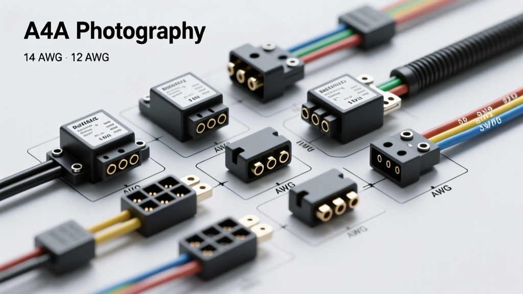
Introduction to A4A Auto Electric Components
When designing or upgrading high-amperage auxiliary circuits in modern vehicles, the ubiquitous 30A ISO mini relay often falls short. Accessories like dual-cylinder onboard air compressors, heavy-duty winch solenoids, and high-CFM electric cooling fans draw massive inrush currents that can easily weld the contacts of standard relays. This is where A4A auto electric components enter the workflow. Engineered for extreme vibration, high thermal loads, and severe moisture ingress, A4A auto electric relays and their corresponding weather-sealed connector harnesses provide a robust alternative to generic, off-the-shelf automotive electrical parts.
In this comprehensive selection guide, we will compare A4A auto electric heavy-duty relays and connector systems against standard ISO and Delphi-style equivalents. We will cover specific pin configurations, wire gauge (AWG) requirements, terminal crimping methodologies, and real-world troubleshooting for high-draw 12V and 24V automotive circuits.
A4A Relays vs. Standard ISO Mini Relays: Technical Comparison
The most common failure point in auxiliary automotive wiring is the relay contact welding shut due to arc suppression failure during high inrush events. Standard Bosch-style ISO mini relays typically utilize Silver Nickel (AgNi) contacts. While adequate for lighting or fuel pumps, AgNi contacts are highly susceptible to welding when subjected to the 60A+ inrush spikes of an electric motor starting under load. A4A auto electric heavy-duty relays utilize Silver Tin Oxide (AgSnO2) contact materials, which offer vastly superior arc-quenching properties and resistance to contact welding.
| Specification | Standard ISO Mini Relay (Generic 30A) | A4A Auto Electric Heavy-Duty (50A/80A) |
|---|---|---|
| Max Continuous Current | 30 Amps | 50A (Standard) / 80A (High-Capacity) |
| Contact Material | Silver Nickel (AgNi) | Silver Tin Oxide (AgSnO2) |
| Coil Resistance (12V) | 75 - 90 Ohms | 65 - 75 Ohms (Heavy copper winding) |
| Ingress Protection | IP54 (Unsealed / Splash resistant) | IP67 / IP69K (Fully Potted & Sealed) |
| Terminal Blade Width | 6.3mm (1/4 inch) | 9.5mm (3/8 inch) for load pins |
| Coil Suppression | Resistor or None | Integrated Bidirectional Zener Diode |
For deeper insights into relay contact materials and arc suppression, refer to the Littelfuse Automotive Relay Standards documentation, which outlines the thermal limits of AgSnO2 versus AgNi in DC switching applications.
Wiring the A4A 50A Heavy-Duty Relay: Pinout and AWG Sizing
Proper wire sizing is critical when deploying A4A auto electric components. Because these relays are rated for higher continuous loads, the wiring feeding the load pins must be upgraded accordingly to prevent voltage drop and thermal melting. According to SAE J1128 standards, wire gauge must be selected based on the length of the run and the maximum continuous amperage.
Standard 5-Pin SPDT Configuration
- Pin 30 (Common / Power Input): Connect to the main battery positive via a primary fuse. Wire Spec: 10 AWG or 8 AWG (Red), depending on run length. For runs exceeding 10 feet, step up to 8 AWG to maintain a voltage drop below 0.5V.
- Pin 87 (Normally Open / Load Output): Connect to the positive terminal of the accessory (e.g., compressor motor). Wire Spec: 10 AWG (Blue).
- Pin 87a (Normally Closed): Typically unused in high-draw auxiliary circuits. If used for secondary logic, 16 AWG is sufficient.
- Pin 86 (Coil Positive): Connect to the switched 12V source (e.g., dashboard toggle switch or ECU trigger). Wire Spec: 16 AWG (Yellow).
- Pin 85 (Coil Ground): Connect to a clean, bare-metal chassis ground. Wire Spec: 16 AWG (Black).
Expert Tip: Never route the heavy 10 AWG load wires (Pins 30 and 87) in the same loom as sensitive CAN-bus or audio signal wires. The electromagnetic interference (EMI) generated by the high-current switching of an A4A relay can induce noise in low-voltage data lines.
Connector Selection: A4A Weather-Seal vs. Delphi Weather-Pack
The reliability of an A4A auto electric relay is entirely compromised if the connector harness suffers from moisture ingress or terminal fretting. While the legacy Delphi (now Aptiv) Weather-Pack system has been the industry standard for decades, A4A Weather-Seal connectors offer distinct advantages for high-vibration, high-amperage environments.
Comparative Connector Architecture
The Aptiv Weather-Pack Connector Specifications highlight a robust silicone ribbed seal design. However, standard Weather-Pack terminals are typically rated for a maximum of 20A per circuit. When pushing 40A+ through a single cavity, standard Weather-Pack terminals can overheat, causing the nylon housing to become brittle and the silicone seals to melt.
A4A Weather-Seal connectors utilize a high-temperature PBT (Polybutylene Terephthalate) housing and feature wider, open-barrel crimp terminals designed specifically for 10 AWG and 8 AWG wire. The secondary locking tang (TPA - Terminal Position Assurance) on A4A connectors ensures that the heavy-gauge wires cannot back out of the housing when subjected to the stiff bending radius of thick 10 AWG automotive wire.
Proper Crimping Methodology
Do not use insulated terminal crimpers or pliers on A4A open-barrel terminals. You must use a dedicated open-barrel crimping tool (such as the TE Connectivity AMP or equivalent ratcheting crimper). The crimp must feature a distinct 'B' or 'M' shape cross-section, ensuring the wire strands are compressed tightly against the terminal walls without cutting into the copper core. After crimping, slide the silicone cavity seal up to the insulation grip and insert the terminal into the housing until you hear a definitive mechanical click.
Real-World Application: Auxiliary Air Compressor Circuit
Consider the installation of a heavy-duty dual-cylinder onboard air compressor (e.g., ARB CKMTA12 or VIAIR 400 series). These units draw roughly 15A to 20A continuously, but their locked-rotor inrush current can spike to 65A upon startup.
Circuit Design and Protection
- Primary Protection: Install a 60A MAXI fuse or an ANL fuse within 18 inches of the battery positive terminal. This protects the main 8 AWG feed wire against dead shorts.
- Relay Selection: Use an A4A auto electric 60A sealed relay. The AgSnO2 contacts will easily swallow the 65A inrush spike without micro-welding.
- Switching Logic: Run a 16 AWG wire from a fused ignition source to a dashboard switch, then to Pin 86. Ground Pin 85 to the chassis.
- Thermal Management: Mount the A4A relay in a location with ambient airflow. While the relay is IP69K sealed and can be mounted in the engine bay, keeping it away from direct exhaust manifold radiation will extend the life of the internal coil winding insulation.
Troubleshooting Common A4A Circuit Failures
Even with premium A4A auto electric components, installation errors can lead to circuit failures. Use the following diagnostic decision tree to isolate issues in heavy-duty relay circuits.
Symptom: Relay Clicks, but Accessory Does Not Engage
- Cause 1: Voltage drop across the load circuit. The coil requires only 150mA to pull in, so it clicks, but the 10 AWG load wire has a bad crimp or corroded terminal at Pin 30 or 87.
- Fix: Perform a loaded voltage drop test. Place multimeter probes on the battery positive and Pin 87 output while the circuit is under load. A reading above 0.5V indicates high resistance in the feed wire or fuse holder.
- Cause 2: Undersized primary fuse blowing instantly under inrush.
- Fix: Verify the inrush rating of the accessory and upgrade to a slow-blow MAXI fuse or ANL fuse that tolerates momentary spikes.
Symptom: Relay Fails to Disengage (Accessory Runs Continuously)
- Cause 1: Contact welding. If a generic relay was used instead of an A4A AgSnO2 relay, the contacts have likely fused.
- Fix: Replace with a genuine A4A auto electric heavy-duty relay and verify the flyback diode in the circuit is functioning.
- Cause 2: Short to power on the coil ground wire (Pin 85).
- Fix: Disconnect the 16 AWG ground wire from Pin 85. If the relay drops out, trace the wire for chafing against a 12V source.
Symptom: ECU or Dashboard Switch Burns Out
- Cause: Inductive kickback. When the relay coil is de-energized, the collapsing magnetic field generates a high-voltage reverse spike (flyback voltage) that can exceed 100V, instantly frying sensitive solid-state ECU drivers or dashboard switches.
- Fix: Ensure the A4A relay specified includes an internal bidirectional Zener diode or freewheeling diode. If using a relay without internal suppression, solder a 1N4007 flyback diode across the coil terminals (Stripe to Pin 86, Anode to Pin 85) to safely recirculate the inductive spike.
Conclusion
Upgrading to A4A auto electric relays and weather-sealed connectors is a non-negotiable best practice for any automotive circuit drawing over 30A continuously or experiencing high inrush currents. By matching the correct AgSnO2 contact relay with properly crimped 10 AWG open-barrel terminals and adhering to strict voltage-drop limits, you ensure that your auxiliary lighting, winching, and pneumatic systems operate reliably in the harshest off-road and engine-bay environments.